调频发射电路-----FM Transmitter


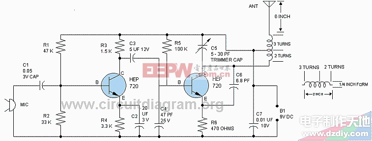
This is a circuit diagram of FM microphone speak in microphone and hear your voice on FM receiver. The circuit contains microphone preamp for increasing the signal of weak sounds. If you wind the coil correctly then the circuit will perform very well. Make coil L1 accurately as shown in diagram. If you want good speech quality use ceramic or crystal microphone.
The circuit is using two transistors Q1 and Q2. The transistor Q1 is used to amplify the signals coming from microphone after increasing the audio signals coming from microphone transistor Q1 send them to transistor Q2 base. Transistor Q2 is an RF oscillator.
This circuit can be assembled on vero board. Fit the circuit in metal case to save from hand capacitance which will change the output frequency. Make a hole in metal case for passing the antenna from the metal case. Do not make more gap in between components it will poor the performance, make sure that all parts kept as near as possible on circuit board.
评论