单管调频发射电路(英文)-----FM TRANSMITTER


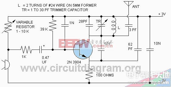
A best designed circuit of an fm transmitter to broadcast your music or voice around the house and yard. There are many circuits of fm transmitter on internet but some are very big circuits containing lots of coils and components, some drift their frequency, some eats battery very fast, some are small low power but not perform well and range is very short. This circuit is not only long range as compare to other one transistor fm transmitters but also very stable and energy saver. Many fm transmitter circuits use two transistors for increasing the microphone signal to hear weak sound signals but the good thing of this circuit is that it uses only one transistor and the microphone circuit is very sensitive to hear very weak or small voices. The circuit is designed to take very low power from battery and broadcast a good strong signal on the fm band from 103 MHz to 108 MHz but you can change frequency width by making some experiments with coil. For antenna use any wire of 20 to 30 centimeters, for increasing range further fit the circuit in a metal box and use 80 centimeters wire as antenna and do not wound the wire of antenna keep it vertical, keep the leads of the components short and solder them as near as possible on PCB. The variable resistor (1 -10 K) near microphone is to adjust the microphone voice quality, adjust the variable resistor to any value where you get best quality and use fix resistor of that value in the place of variable resistor. Or if you want to use fix resistor in the place of variable resistor and don't want to adjust the sound quality then use 5K resistor. If you want to make microphone more sensitive then remove the 1K resistor near microphone. If you don't want sensitive microphone and want to use microphone from near then change the value of 1K resistor to 10K.
评论