2米调频144M-148M发射电路


2米调频144M-148M发射电路
Near-Earth Telemetry
(Morse Code Telemetry)
2 meter FM - 144mHz - 148mHz
Altitude, Temperature and Radiolocation for Small Rockets and Aircraft
Update #1 Modification - the signal output can be significantly improved by replacing C2 with a 22 picofarad capacitor and by adding a 4.7 picofarad capacitor between the collector and emitter of Q1.This modification was developed using the 49.152 computer crystal (815-ABLS-49.152-B2 from Mouser.com). It has not been tested with the custom 3rd overtone crystal. Also, the 4.7 picofarad capacitor is not always required.
Update#2 - Inexpensive computer crystals can be used in this circuit. See "transmitter" secession for parts reference or click link.
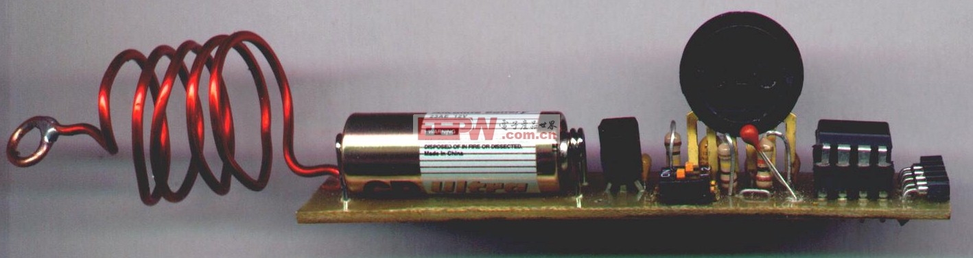
The following files and "Quick" plans describe a telemetry system consisting of a transmitter with "interchangeable" sensor modules.Range is 1600 feet (6 ft above ground to 6ft above ground) and 2500 feet air to ground (as measured using a ICOM IC-W32A HT with the standard 8" antenna. It might be higher. This is the maximum altitude tested so far).
This is still a a-work-in-process so your comments will be appreciated. e-mail to jerry_baumeister@msn.com
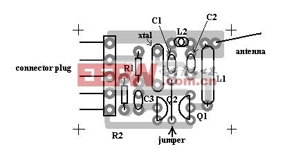
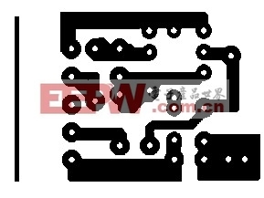
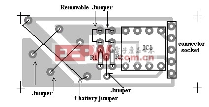
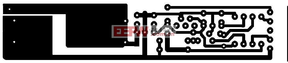
- The circuit is designed for a printed circuit board (PCB) assembly. The foil patterns are provided in the following plans. However, other parts layouts may work as well.
- The system is comprised of a transmitter that plugs into a " control and sensor" (CS) module. The CS modules carry the battery, microcontroller and the sensors. Two different CS modules are provided with the following plans. One module measures and transmits atmospheric pressure (altitude) and temperature. The other module has no sensors and is designed for radiolocation only (it's smaller and uses less power).
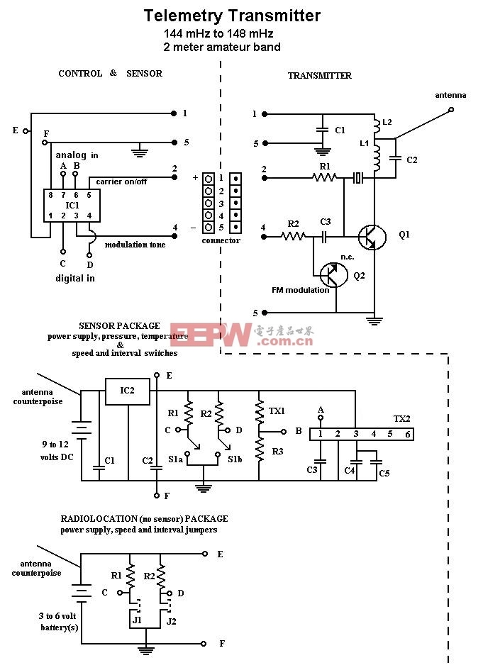
TRANSMITTER
The transmitter is a crystal controlled 2 meter (144 MHz - 148 MHz) transmitter. It can be either FM modulated or On-Off-Carrier (OOC) modulated ie. CW. The transmitter is controlled by the microprocessor located on the CS module. The crystal is a third overtone series mode crystal. The software only supports FM modulation at this time.
You can use a microprocessor crystal (48 MHz series or 48MHz 20 pF) which cost about 85 cents from Mouser.com. These crystals will result in a transmitter frequency of from 144.000 MHz to 144.010 MHz. Be sure the frequency is clear when you use these crystals. I have also had good luck with a 49.152 MHz 3rd overtone crystal (Mouser part# 815-ABLS-49.152-B2). It is a surface mount type but you can carefully bend the leads out straight and use in this circuit. It cost 45 cents (so buy two). This crystal will operate on 147.460 MHz. You can order a custom crystal for a specific frequency from a crystal manufacture and can expect o pay about 17.50 each.
CS MODULE (control and sensor module)
The CS module contains the microcontroller, power supply and sensors.
Microprocessor
The microprocessor is a PIC12F675 eight pin Flash microcontroller by MicroChip. It was programmed with MicroChip's MDE-LAB in PIC assembler language on their Flash starter kit. A copy of the source code is available for downloading, click telemetry.asm .
The program is structured as a series of "calls" to subroutines and is easily modified. Basically the program:
1. Turns the transmitter “on” and “off” by bring pin 5 high or low
2. Modulates the oscillator by placing a tone out pin 3 in Morse code format.
3. Uses pins 6 and 7 as A/D inputs from analog sensors
4. Uses pin 2 as a speed-of-transmission selection switch (either 8 WPM or 50 WPM)
5. Uses pin 4 as an intermittent transmission selection switch. If high then the transmitter will wait 60 secondsbetween transmissions.
Power Supply
The CS module with the sensors requires a regulated power supply and uses a 78L05 IC for this purpose. The smaller "no-sensor" CS module does not require voltage regulation, since it has no sensors, and can run directly from one or two BR1632 lithium "coin" cells.
The 23A "lighter" battery used on the larger CS module will only last about 1.5 hours with continuous operation. So if longer operation is required a heaver battery like the common 9 volt radio battery can be used. Of course this adds considerably more weight to the system.
Sensors
One of the CS modules has an atmospheric pressure sensor and a thermister for sensing temperature.
Data protocol
The data is transmitted in Morse code. Morse code was selected in this design because it could be directly read without additional hardware and it could also be read using a wide array of software and stand alone hardware. The rate of transmission is switch selectable at either 8 WPM for humans or 50 WPM for machine copying.
Data
The data transmitted is in the units produced by the Analog to Digital Converter (ADC) in the microcontroller. Since the ADC is a 10 bit format it generates a number between 0 and 1024 which proportionally represents the voltage it measures, in this case the voltage generated by the sensors. This data can be converted to altitude by downloading Excel charts (AltConv.zip). If you want to do the math use...
p= sea level pressure obtained from your local weather station or NOAA broadcast in inches of mercury
p1h= first reading (ground level)
p2h=lowest reading (maximum altitude)
convert to inches of mercury by
p1h= ( A/D reading * 0.032047)+3.11754 Converts the A/D reading to inches of Mercury
p2h= ( A/D reading * 0.032047)+3.11754 Converts the A/D reading to inches of Mercury
preflight altitude at lunch site =[10log(p1h/p)/5.2558797]-1/ (-6.875,5856 x 10-6)
post flight maximum altitude =[10log(p2h/p)/5.2558797]-1/ (-6.875,5856 x 10-6)- If you don't want to do all the math and close is good enough then multiply P1minus P2 by 32. (P1-P2)*32
For a temperature conversion chart (A/D units to degrees C or F) click here.
The Morse code data stream is as follows:
"a" followed by the current pressure (altitude)
"at" follwed by the minimum pressure recorded since power on (maximum altitude reached)
"b" followed by the temperature
Your station call sign (must be programmed into the firmware)
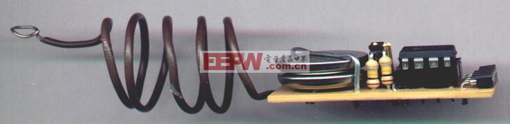
Antenna
The transmitter antenna is 12 inches of 22 to 26 gauge common "hook-up" wire. The range of the transmitter can be doubled by providing a counterpoise consisting of a wire of the same length as the antenna from the positive battery on the CS module extending in the opposite direction of the antenna. Both the counterpoise and the transmitter antenna can be coiled on a 3/4 inch diameter to shorten the length of the antenna in order to allow storage inside a payload compartment. Coiling the antenna does shorten the range of the transmission.
A method that works well in most cases is to suspend the module from the nose cone by the coiled counterpoise on the CS module, and extend the transmitter antenna out the bottom of the payload compartment and along side the fuselage. The coiled counter poise provides a shock absorbing function during lift-off and the external transmitting antenna provides optimum range of transmission.
Schematic
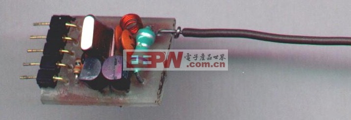
Transmitter parts
 |
0.9" x 0.6" | |||
| Resistors | Value | Part number | Supplier | Comments |
| R1 | 100K 1/8 watt | 299-100K | Mouser | |
| R2 | 10K 1/8 watt | 299-10K | Mouser | |
| Capacitors | ||||
| C1 | .001 mF | 21RX510 | Mouser | |
| C2 | 22pF | 21RD747 | Mouser | |
| C3 | 15pF | 80-C315C150J1G | Mouser | |
| Semiconductors | ||||
| Q1 | NTE107 | 526-NTE107 | Mouser | |
| Q2 | NTE108 | 526-NTE108 | Mouser | |
| Crystal | ||||
| xtal | 144 – 148 Mhz third overtone series crystal | EX45DL00 | ICM (International Crystal Manufacture) | |
| ICM HC-45/U SERIES | ||||
| (FX=20.00-59.99MHZ) | ||||
| xtal | 49.152 MHz 3rd overtone crystal | (Mouser part# 815-ABLS-49.152-B2) | Mouser | operates at 147.460 MHz |
| xtal | 48 MHz series or 48MHz 20 pF micro processor crystal | Mouser | operates at 144.01 MHz | |
| Inductors | ||||
| L1 | 0.68 microHenry | 434-22-R68 | Mouser | |
| L2 | 4 turns tightly wound on 1/8"dia. | |||
| Miscellaneous | ||||
| PCB | ||||
| antenna | 12 inch | |||
| header | 64 single row right angle header .100 | 575-643909 | Mouser | Remove and use 5 of the headers |

sensor and control module parts
 N0-sensor module ( power supply and microcontroller) | ||||
 foil 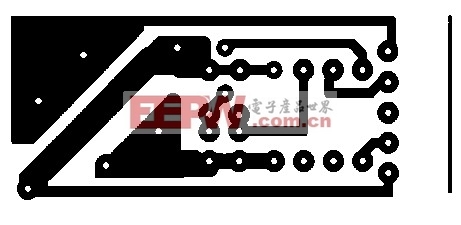 reversed foil  1.5" x 0.6"
| ||||
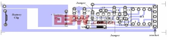 altitude and temperature module | ||||
| Value | Part number | Supplier | Comments | |
| Resistors | ||||
| R1 | 100K 1/8 watt | 299-100K | Mouser | |
| R2 | 100K 1/8 watt | 299-100K | Mouser | |
| R3 | 10K 1/8 watt | 299-10K | Mouser | |
| Capacitors | ||||
| C1 | 0.1 mF | 21RX310 | Mouser | |
| C2 | 0.1 mF | 21RX310 | Mouser | |
| C3 | 470 pF | 80-C315C471J2G | Mouser | |
| C4 | .01 mF | 21RX410 | Mouser | |
| C5 | 1 mF | 80-T350A105K025 | Mouser | |
| Semiconductors | ||||
| IC1 | PIC12F675 8- pin FLASH- Based 8-bit CMOS Microcontroller | 579-PIC12F675-I/P | Mouser | |
| IC2 | 78L05 5 volt regulator | 511-L78L05ABZ | Mouser | |
| Sensors | ||||
| TX1 | Thermistor | 71-01C1002FP | Mouser | |
| TX2 | Absolute pressure sensor 0 – 15 PSI | MPX4115A-ND | DigiKey | |
| Miscellaneous | ||||
| PCB | 2 pos SPST dip switch | 653-A6T-2104 | Mouser | |
| S1 a&b2 | 64 single row right angle socket .100” | 575-643903 | Mouser | Remove and use 5 of the headers |
| Socket | 64 single row right angle socket .100” | 575-643903 | Mouser | Remove and use 5 of the headers |
| Header | 2 single row straight header .100” | 649-69190-202 | Mouser | |
| J1, J2 | Low-profile shunt jumper | 649-687886-202 | Mouser | |
| battery | 12V | 573-23A | Mouser | |
| battery | 3 volt lithium | 658-BR1632 | Mouser | |
| Firmware | telemetry.asm | |||
| PIC 12F675 Programming software | MPLAB-IDE | Microchip | ||
| PIC 12F675 Programmer | PICKIT 1 8/14-Pin Flash Starter Kit | 597-DV164101 | Mouser | Includes MPLAB-IDE |

评论