ActiveHigh-VoltageTransientProtectorsTrumpConventionalApproachesinAutomo...
Abstract: Most vehicle electronic systems require overvoltage, reverse-battery, and transient protection. The use of active protectors for these purposes offers substantial advantages in power dissipation, optimization of the operating voltage limits, part cost savings, and the reduction of quiescent current. This article details the benefits of active over conventional protection circuits.
IntroductionVarious electric and electromagnetic disturbances generated inside and outside a car can be hazardous to vehicle electronic equipment. They can degrade performance, cause malfunctions, and even destroy electronic devices. The most severe disturbances—large positive and negative overvoltages and transients—can be generated in the vehicle's electrical system itself or be applied to it from external sources due to (erroneous) human interaction.
Transient Voltages Generated Inside the CarIn an automotive network, electronic control units (ECUs) are interconnected through the wiring harness. Most ECUs are powered by the car battery, either directly or through the ignition switch. Even during normal operation, electrical disturbances and high-frequency effects can occur, and be distributed across the wiring harness to the src="/data/attachment/portal/201007/ET27222201007210939571.gif">
Figure 1. Typical load-dump surge shape: a) unsuppressed; b) suppressed.
Jump Start, Cold Crank, and Battery ReversalAnother danger is the "double battery" voltage that can be applied during a jump start, i.e., when hooking up with jumper cables to another vehicle's battery with a 24V network system, so that you end up using a 24V battery to start a 12V system. Consider the following situation: you crank the engine, especially in cold weather and with a partly charged battery, and the engine oil has become very thick. The engine cranking requires the starter to deliver more torque, which, in turn, needs more current from the battery. This large current load causes a brief "dip" in supply voltage, a dip that can depress the voltage from a nominal 12V to less than 5V. This reduction can last for several tens of milliseconds, causing electronic systems to temporarily suspend operation (Figure 2). src="/data/attachment/portal/201007/ET27222201007210939572.gif">
Figure 2. Typical vehicle cold crank voltage shape.
An additional hazard that vehicle electronics must withstand is battery-polarity reversal, which can occur when a battery is incorrectly attached to the electrical system (e.g., -14V).
Protection Against Improper Power LevelsThe disturbances mentioned above create a need for protection against improper voltages. Analysis shows that the load-dump pulse is the most energy-rich type of disturbance. To protect electronic modules against destruction by this pulse, two protection methodologies are used today:
- Clamp the voltage centrally for all modules at the vehicle alternator (central load-dump suppression, Figure 1b).
- Provide a protection circuit src="/data/attachment/portal/201007/ET27222201007210939573.gif">
Figure 3. Transient voltage suppressor characteristic (VBR = breakdown voltage, VC = clamping voltage @ peak pulse current, IP).
VaristorsVaristors are voltage-dependent resistors (VDRs). They are symmetrical, nonlinear resistive elements whose resistance decreases abruptly above a certain voltage (Figure 4). In clamping both positive and negative voltages, their behavior is similar to two back-to-back zener diodes. They handle high levels of current and energy for their small size and cost, but they exhibit relatively high leakage current as the applied voltage approaches the clamping voltage. The clamping voltage also increases significantly with applied current. Varistors degrade from repeated exposure to surges, and generally have a higher "clamping voltage" and a significantly slower reaction time compared to TVS diodes.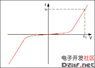
Figure 4. Typical varistor characteristic (VC = clamping voltage @ peak pulse current, IP).
Discrete Protection CircuitsA simple and cost-effective way to protect sensitive circuitry is to parallel the load with a clamp such as a TVS diode and a capacitor preceded by a fuse (Figure 5). This circuit protects the ECU against transient overvoltages and load-dump voltages above the breakdown voltage of the TVS diode (D1). When exposed to high-energy negative transients or steady-state reverse voltages, the TVS is biased in the forward direction, thus protecting downstream circuitry by limiting the negative voltage to its forward bias voltage (e.g., -1V). Repetitive low-energy negative transients, such as induced by relay or solenoid switching, are filtered by the capacitor (ClowE). If either negative or positive overvoltages persist, the fuse will blow.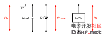
Figure 5. A simple overvoltage protection circuit using a filter capacitor, transient suppressor diode, and fuse.
To avoid having to replace a fuse in the vehicle's fuse box or in an inaccessible ECU, and to ensure continuous ECU operation, other techniques must be employed, such as additional series protection. The circuit of Figure 6 protects the ECU against reverse-battery conditions and transient negative voltages (D2) and impulse positive overvoltages (load dump and low energy transients) greater than the breakdown voltage of the TVS diode (D1). Note that for D2 you must choose a peak reverse voltage greater than the largest possible negative transient.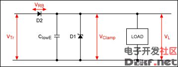
Figure 6. By replacing the fuse used in Figure 5 with a diode, this circuit provides overvoltage protection. It also protects against negative transients and reverse battery connections.
Because of their small dimensions, low cost, and high energy-absorption capability, varistors are often chosen for applications in which board space is critical and the downstream circuitry has some tolerance for positive and negative overvoltages. The circuit of Figure 7 protects the downstream circuitry from overvoltage pulses (positive and negative transients) greater than the breakdown voltage of the varistor. The capacitor helps filter low-energy positive and negative transients.
Figure 7. When board space is limited, a varistor (in this case, a VDR) can be used instead of a TVS diode when you want to protect the downstream circuitry from overvoltage pulses (positive and negative transients) greater than the breakdown voltage of the varistor. In this case, the downstream circuits must have some tolerance for positive and negative overvoltage occurrences.
Advantages and Disadvantages of Discrete Protection CircuitsAll of the above circuits have advantages and disadvantages. Figure 5 shows a simple transient protector circuit, consisting src="/data/attachment/portal/201007/ET27222201007210939578.gif">
Figure 8. The MAX16013 and MAX16014 provide active transient protection by monitoring the input voltages src="/data/attachment/portal/201007/ET27222201007210939579.gif">
Figure 9. The MAX16013/MAX16014 are used as the main switch to reduce quiescent current consumption if an ECU is in OFF mode.
SummaryThe use of active overvoltage protectors can be an advantage in some applications. These devices offer significant benefits in reduced power dissipation, output power gain (performance), low-voltage operation (cold crank), lower quiescent current, and lower cost for the downstream circuitry.
¹Related parts: MAX6397/MAX6398/MAX6399, MAX6495–MAX6499.
A similar article was published the February, 2008 edition of Auto Electronics Magazine, a Penton Publication.Transil is a registered trademark of ST Microelectronics.
TransZorb is a registered trademark of Vishay Intertechnology, Inc.
-- END: DB HTML --


评论