汽车线性稳压器静态电流最小化-AutomotiveLinearRegulatorsMinimizeQuiescentCur...
Abstract: Many automotive mechanical functions have been replaced or amended by electronic circuits in recent years. src="/data/attachment/portal/201007/ET27224201007210939581.gif">
Figure 1. This typical load-dump overvoltage pulse reaches a maximum amplitude (Vs) of 36V in cars and 58V in trucks. Its duration (td) is several hundred milliseconds.
Power Dissipation and TemperatureThese high input-voltage levels lead us directly to the next point to consider. The linear regulator not src="/data/attachment/portal/201007/ET27224201007210939582.gif">
Figure 2. This small but powerful automotive linear regulator comes in a 6-pin TDFN package, and can dissipate up to 1.9W. At the maximum-allowed ambient temperature (+125°C) it can dissipate 600mW.
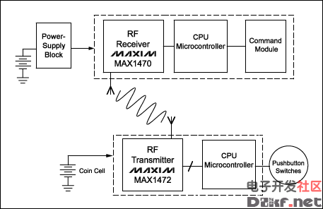
Lowest Possible Quiescent Current for Always-On FunctionsThe receiver of a remote keyless entry (RKE) system (Figure 3) must be always active, so at any time it can detect the commands issued by the remote controller in the key. You cannot disable the power supply of an RKE receiver, so its circuitry should draw the lowest possible quiescent current, especially in stand-by mode. It must then supply a normal operating current as soon as it awakens.

Figure 3. A typical RKE system consists of the car-mounted side and the key-mounted side. Because the car's power supply block connects directly to the battery, its quiescent current must be low.
We must, therefore, optimize the power supply block (top left corner) in terms of minimizing quiescent current. Aside from low quiescent current, requirements src="/data/attachment/portal/201007/ET27224201007210939584.gif">
Figure 4. This automotive linear regulator requires a minimum number of pins and external components, minimal board space, and a minimum (typical) no-load supply current of 9.5µA.
Power-Dissipation ProblemsTo save board space and cost, designers sometimes avoid the use of a switch-mode power supply, even when the application is pushing the linear regulator to the edge of its power-dissipation capability. Consider, for example, an automotive electrical control unit (ECU) that requires a 5V supply voltage. The ECU normally includes a microcontroller, a sensor, and a CAN driver or other bus-interface device with minor analog circuitry connected to it. It might draw 150mA of supply current in full operation.
A linear regulator with 13V nominal input voltage can, therefore, dissipate 1.2W, and that level can rise briefly to 4W during a load dump. To handle the nominal 26V found in a truck, the regulator must dissipate more than 3W continuously. For these applications, another automotive linear regulator (MAX5087) has been designed for output currents as large as 400mA. It also comes in a larger 8mm x 8mm, 56-pin QFN package that boosts the allowable power dissipation to 3.8W (Figure 5).
Figure 6. This automotive linear regulator contains two linear regulators plus a set of "housekeeping" functions. It can dissipate 2.7W at 70°C.
Figure 1. This typical load-dump overvoltage pulse reaches a maximum amplitude (Vs) of 36V in cars and 58V in trucks. Its duration (td) is several hundred milliseconds.
Power Dissipation and TemperatureThese high input-voltage levels lead us directly to the next point to consider. The linear regulator not src="/data/attachment/portal/201007/ET27224201007210939582.gif">
Figure 2. This small but powerful automotive linear regulator comes in a 6-pin TDFN package, and can dissipate up to 1.9W. At the maximum-allowed ambient temperature (+125°C) it can dissipate 600mW.
Lowest Possible Quiescent Current for Always-On FunctionsThe receiver of a remote keyless entry (RKE) system (Figure 3) must be always active, so at any time it can detect the commands issued by the remote controller in the key. You cannot disable the power supply of an RKE receiver, so its circuitry should draw the lowest possible quiescent current, especially in stand-by mode. It must then supply a normal operating current as soon as it awakens.

Figure 3. A typical RKE system consists of the car-mounted side and the key-mounted side. Because the car's power supply block connects directly to the battery, its quiescent current must be low.
We must, therefore, optimize the power supply block (top left corner) in terms of minimizing quiescent current. Aside from low quiescent current, requirements src="/data/attachment/portal/201007/ET27224201007210939584.gif">
Figure 4. This automotive linear regulator requires a minimum number of pins and external components, minimal board space, and a minimum (typical) no-load supply current of 9.5µA.
Power-Dissipation ProblemsTo save board space and cost, designers sometimes avoid the use of a switch-mode power supply, even when the application is pushing the linear regulator to the edge of its power-dissipation capability. Consider, for example, an automotive electrical control unit (ECU) that requires a 5V supply voltage. The ECU normally includes a microcontroller, a sensor, and a CAN driver or other bus-interface device with minor analog circuitry connected to it. It might draw 150mA of supply current in full operation.
A linear regulator with 13V nominal input voltage can, therefore, dissipate 1.2W, and that level can rise briefly to 4W during a load dump. To handle the nominal 26V found in a truck, the regulator must dissipate more than 3W continuously. For these applications, another automotive linear regulator (MAX5087) has been designed for output currents as large as 400mA. It also comes in a larger 8mm x 8mm, 56-pin QFN package that boosts the allowable power dissipation to 3.8W (Figure 5).
Figure 6. This automotive linear regulator contains two linear regulators plus a set of "housekeeping" functions. It can dissipate 2.7W at 70°C.


评论
学习了。