过电压保护汽车系统-Overvoltage Protecti

Abstract: Vehicle electronics system components such as sensors and actuators require protection against over voltage, transient voltage and reverse voltage conditions. This application note discusses some discrete circuit protection schemes suitable for use with Maxim sensor conditioning ICs. It is a common requirement for electronic circuits to have to withstand some degree of overvoltage and/or reverse voltage on the power-supply lines. This is especially true with automotive systems where the main power-supply input to any particular vehicle electronic system is required to tolerate various overvoltage and transient voltage conditions, including alternator load dump. Components within the electronic system that are downstream of the main power supply are then protected from the worst of the power-supply conditions. Such components, when mounted remotely from the main electronic module, have additional wiring fault tolerance requirements due to their proximity to the vehicle's wiring loom.Components mounted remotely from the main electronics module include sensors and actuators, which are commonly required to tolerate the application of ±16V across any combination of their exposed connections. The purpose of this test is to simulate wiring-loom faults that result in wiring shorts to the vehicle's battery connections.Many modern integrated circuits are designed to operate from a nominal 5V power supply and do not readily accept the application of ±16V to their pins. Some kind of protection circuit is therefore needed. Any overvoltage protection circuit will be required to do two basic things. The first is to prevent voltages greater than the maximum allowable from being applied to the IC pins. A trip voltage value (the power-supply voltage above which the protection circuit will activate) is therefore required that will allow the system to function with normal power-supply voltages. The second task is for the protection circuit not to intrude on the normal function of the circuit. This second point is concerned primarily with power-supply voltage drops induced by the protection circuit. These are most important in ratiometric measurement systems where any power-supply voltage drop will appear as an offset in the associated measurement. In addition to these two basic points, the protection circuit must be fast enough to act on any transient events that can occur on the power-supply line. A discrete component circuit that fulfills these overvoltage requirements is presented in Figure 1.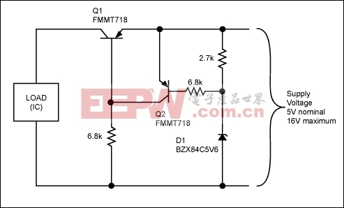 The circuit operates to disconnect the load during overvoltage conditions. That is to say that Q1 switches off when an overvoltage condition is detected, removing power from the load. Q1 will turn on again when the overvoltage condition is removed. One of the attractions of this type of circuit is in its response speed. The circuit in Figure 1 does not use feedback, so there are no high-order damping effects or slew-rate limitations to overcome. The full speed of the constituent parts is available to prevent transient power-supply events from reaching the load.Q2 has been chosen, for convenience, to be the same type as that chosen for Q1, although there are no special requirements of this device and almost any PNP device could be substituted.
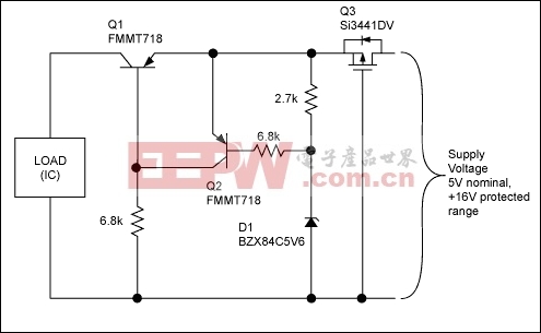
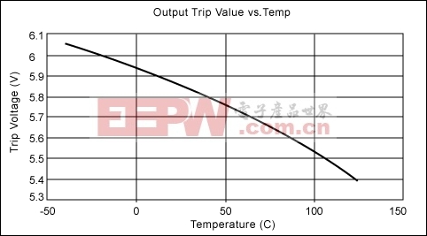 The reverse-voltage protection characteristic of the circuit in Figure 2 can be characterized by the reverse leakage measured over temperature with -16V applied to the power input. The results obtained for reverse-leakage performance of the circuit in Figure 2 are shown in Table 1, in which the reverse-leakage characteristic is presented as a leakage-resistance value. Table 1. Reverse-Leakage Resistance versus TemperatureNote: The reverse-leakage current measured from -40°C to 60°C was effectively zero (infinite-leakage resistance).The forward voltage drop of the protection circuit in Figure 2 was measured at three supply voltages—4.5V, 5V, and 5.5V—for temperatures in the -40°C to 125°C range. The results obtained are presented in the graph in Figure 4.
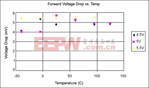 Examining the results in Figure 4 shows the forward voltage drop of the circuit in Figure 2 to be below 6mV for temperatures in the -40°C to 125°C range. The effect of power-supply voltage drops on ratiometric measurement errors is the same as with any other system offsets, so long as the circuit has been calibrated with the protection circuit in place. When subjected to a 10% change in power-supply voltage, the error induced by any offset within the system will be 10% of the offset value. So, a 6mV offset (voltage drop) will induce a ratiometric measurement error of 0.6mV when the power supply is changed by 10%. In a system where the output span is set to 4V, this 0.6mV error will correspond to a measurement error of 0.015% of span.
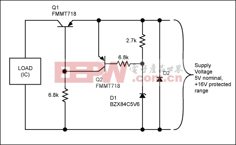
 The circuit operates to disconnect the load during overvoltage conditions. That is to say that Q1 switches off when an overvoltage condition is detected, removing power from the load. Q1 will turn on again when the overvoltage condition is removed. One of the attractions of this type of circuit is in its response speed. The circuit in Figure 1 does not use feedback, so there are no high-order damping effects or slew-rate limitations to overcome. The full speed of the constituent parts is available to prevent transient power-supply events from reaching the load.Q2 has been chosen, for convenience, to be the same type as that chosen for Q1, although there are no special requirements of this device and almost any PNP device could be substituted.
 Reverse-Voltage Protection
The circuit in Figure 1 will withstand reverse power-supply voltages of only about -5V. The reverse breakdown voltages of the base emitter junctions Q1 and Q2 determine this figure. Additional circuitry is therefore required to provide the (-16V) reverse-voltage protection capability. Either one of two simple additions to the circuit in Figure 1 will provide the necessary reverse-voltage protection. The first method employs a p-channel MOSFET, as shown in Figure 2. By configuring the MOSFET as shown, the device's body diode will automatically conduct when a power-supply voltage of greater than about 0.5V is present. The body diode of this transistor is a necessary feature, as without it the circuit would not start up. The addition of this component provides a disconnect function under reverse-voltage conditions. The only requirements for the reverse protection MOSFET are that it should be a low Ron, logic level type. A Si3441DV device is shown, but any similar device can be substituted.The reverse-voltage protection characteristic of the circuit in Figure 2 can be characterized by the reverse leakage measured over temperature with -16V applied to the power input. The results obtained for reverse-leakage performance of the circuit in Figure 2 are shown in Table 1, in which the reverse-leakage characteristic is presented as a leakage-resistance value. Table 1. Reverse-Leakage Resistance versus TemperatureNote: The reverse-leakage current measured from -40°C to 60°C was effectively zero (infinite-leakage resistance).The forward voltage drop of the protection circuit in Figure 2 was measured at three supply voltages—4.5V, 5V, and 5.5V—for temperatures in the -40°C to 125°C range. The results obtained are presented in the graph in Figure 4.Examining the results in Figure 4 shows the forward voltage drop of the circuit in Figure 2 to be below 6mV for temperatures in the -40°C to 125°C range. The effect of power-supply voltage drops on ratiometric measurement errors is the same as with any other system offsets, so long as the circuit has been calibrated with the protection circuit in place. When subjected to a 10% change in power-supply voltage, the error induced by any offset within the system will be 10% of the offset value. So, a 6mV offset (voltage drop) will induce a ratiometric measurement error of 0.6mV when the power supply is changed by 10%. In a system where the output span is set to 4V, this 0.6mV error will correspond to a measurement error of 0.015% of span. Less Expensive Reverse-Voltage Protection
The circuit in Figure 2 uses a p-channel MOSFET as the reverse-voltage protection element. This has the advantage of disconnecting the load during reverse-voltage events and therefore places no particular requirements on the power supply. A less expensive alternative to this is to use a simple diode connected across the power supply as the reverse protection element. This arrangement is shown in Figure 5, but can be used only where the main system power supply is current-limited or fused. The diode protects the circuit by conducting whenever a reverse voltage is applied to the power-supply inputs of the circuit. The diode must be rated to withstand the maximum current or the fuse rating of the system's power source.
评论