
BH1417调频立体声发射机(英文)-----FM Stereo Transmitter circuit diagram Using BH1417

FM Stereo Transmitter circuit diagram Using BH1417
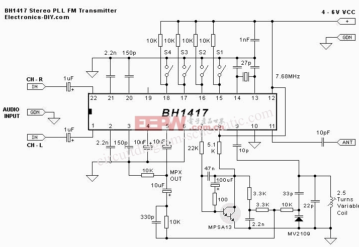
This circuit is a circuit diagram is included in the RF circuit. FM Transmitter circuit diagram using the IC BH1417. Where the integrated circuit design from RHOM which includes many features in one small package. He came with pre-emphasis, limiter so that music can be transmitted in the same audio level, stereo encoder for stereo transmission, low pass filter that blocks audio signals above 15KHz to prevent RF interference, PLL circuit that provides a solid frequency transmission (no more frequency drift), FM oscillator and RF output buffer. The following is a schematic drawing:
There are 14 possible transmission frequencies with 200KHz adding that the user can choose a 4-DIP switch. Band lower frequency ranging from 88.7 to 89.9 MHz, and the frequency band from 107.7 to 108.9 MHz. BH1417 can be given with 4-6 voltage and consumes only around 30mA, provides RF power output of 20mW. BH1417 provides 40db channel separation is quite good, although older BA1404 FM Transmitter chip provides 45dB channel separation a little better.
Source: electronics-diy.com
评论