无线话筒电路图


Couple Notes:
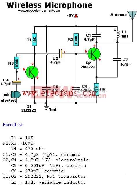
Q1 amplifies input signal via C4 from the electret microphone.
Q2 acts as an oscillator and the signal coming off C2 is fed onto the base of Q2.
L1/C1 is a called 'tank' circuit in the 88MHZ band on your regular AM/FM radio dial.L1 is a 1uH variable inductor ciol be able to tune it a little bit,and the range of 1uH is approximate.
The antenna can be as simple as a 8 "(21cm)piece of wire of and king.
评论