
100W音频放大器电路 (100 W Audio Ampli

100W音频放大器电路 (100 W Audio Amplifier)

General Description
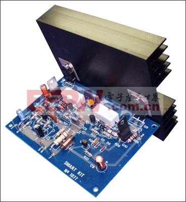
This is an exceptionally well designed amplifier, with a lot of power reserve, high fidelity, low distortion, good S/N ratio, high sensitivity, low consumption and full protection. Having all these almost ideal characteristics this amplifier is likely to become the basic building block of your future high fidelity system, or it can also become the element that will upgrade your existing system.
How it Works
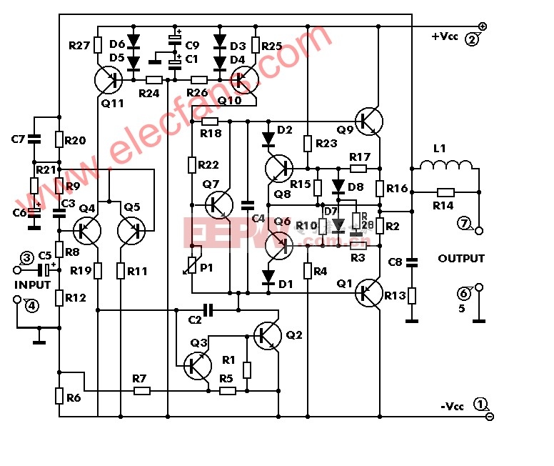
The circuit works from a symmetrical ρ40 VDC power supply and draws a maximum current of 2.6 A. The input circuit of the amplifier is a differential amplifier built around Q4 and Q5 that employ DC feedback thus preventing any DC voltage from appearing across the speaker with the usual destructive results. Q11 acts as a current source and ensures that the input stage draws a constant current of 1 mA. The signal which appears as a voltage drop across the resistor connected in series with the collector of Q4 is used to drive the DARLINGTON pair Q3, Q2 which together with the constant current source of 7 mA that is Q10, form the driver stage. This stage operates in class A and is driving the complementary output stage Q1, Q9. The transistor Q7 is used to balance the circuit at different temperatures and must be mounted on the heatsink between the out put transistors. The feedback loop which consists of R8, R9, C2, C3 provides AC stability to the circuit. The circuit also incorporates a protection stage that makes it virtually indestructible. This protection circuit is built around Q6, Q8. If for whatever reason the output remains connected on one supply rail and the common the output is also protected from high DC voltages that could burn the speakers. The supply rails should be protected by 2 A fuses for the 8 ohm version and 3 A for the 4 ohm.
Technical Specifications - Characteristics
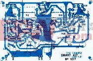
Output power (f=1 KHz, d=0.5 %): 100 W in 8 ohm- You may find sometimes a component with heavier gauge leads than usual, that are too thick to enter in the holes of the p.c. board. In this case use a mini drill to enlarge the holes slightly. Do not make the holes too large as this is going to make soldering difficult afterwards.
- When you finish your work cut off the excess of the component leads and clean the board thoroughly with a suitable solvent to remove all flux residues that still remain on it.
If it does not work
Check your work for possible dry joints, bridges across adjacent tracks or soldering flux residues that usually cause problems. Check again all the external connections to and from the circuit to see if there is a mistake there.
- See that there are no components missing or inserted in the wrong places.
- Make sure that all the polarised components have been soldered the right way round. - Make sure the supply has the correct voltage and is connected the right way round to your circuit.
- Check your project for faulty or damaged components. If everything checks and your project still fails to work, please contact your retailer and the Smart Kit Service will repair it for you.


评论