电容容量测试仪-----Capacitance Meter


这是一个比较复杂的电路.但当你做出来以后。你就有了一个可以用来测量收音机中最大容量电容的测试仪。电容不像电阻把阻值标在外壳上,很多电容的容量都没有在外壳上标出。还有一些旧电容的容量在使用过程中被擦掉了。此仪表可以测量出这些电容的容量,对于电气技术人员、老牌收音机发烧友和无线电爱好者都是好帮手。
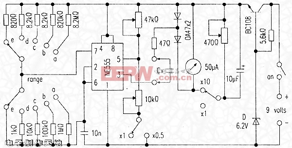
常见的555定时器是此电路的核心部件.它的作用是将被测量电容(Cx)充电到固定电压,然后被测电容通过回路放电,电流表测量出流过47Ω电阻的电流。因为555定时器每秒钟重复这个过程几次。使得电流表的指针保持稳定。
电流会因电容容量的大小而不同.即电流表指针会根据被测电容的容量作相应的偏转,也就是说,电容容量与线路电流的比例是线性的。就像用于测量电压和电流的万用表。 ’
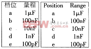
此表有五个挡位,从100pF到1μF,通过一只两极五挡开关切换,另外,开关x10用于测量较大容量的电容,电流分成两路,测量100pF、1000pF、0.01μF、0.1μF或1μF以上电容显示更准确。
元器件的精确度不是十分完善的。即使是最好的器件,一般九只电阻也考虑有2%的误差。如果没有OA47二极管,可用OA91或OA95锗二极管代替。将此电路装入一只塑料盒中.与万用表差不多大。但是稍深一点更好。在财力许可下,测试仪的测量仪表要尽可能大,因为它决定了测量显示的精确度。你购买的电流表量程为0~50微安,但是刻度要从0到100偏转(即原有的刻度10、20、30、40、50用20、40、60、80、100代替),你可以用白色修正液或小纸片修改。
将元器件安装在一块印刷电路板上,555集成块用一只插座连接,以备在需要时方便替换。连接线路要尽可能短,否则线路的杂散电容会降低测量的精度。 ’
可以用已知容量的电容器来校定测试仪,可找一只已知容量的电容,试测几次。如果显示不正确。很简单,只要买几只相同容量的电容,在其中选一只最接近标称容量的用于校正就行了。再用几只最接近标称容量的电容来准确校正各个挡位。
校正时,将x10断开(即两只开关都断开不用),将一只标称电容接入回路。将开关打到合适的量程。调节47kΩ微调电阻,直到准确读出电容的容量。然后合上开关,此时读数会有所变化,调节10kΩ微调电阻,使得两次的读数相等,例如,如果你测量的是一只0.01μF标称电容,在0.1μF档上的读数是10,此时的读数就该是20。
如果不行。就换一只与相应挡位容量相等的电容(如1000pF、0.01μF、0.1μF等)。调节挡位(即1000pF、0.01μF、0.1μF等),使显示的数字为满量程(100)。合上开关x1O,指针的读数会明显下降,调节微调电阻470kΩ,使指针的读数是10。再下调一个挡位(如从0.01μF调到1000pF),指针的读数应该是100。如果不是100,就调节470Ω微调电阻,直到是100为止。此时电容测试仪的校正就完成了,你可以试着测量其他一些电容的容量来验证校正的精确度。
细心测量,多数量程的精度可达5%。
开关x10用于测量10μF及以上大容量的电容;开关×0.5使在测量较小容量的电容时,读数更准确。
Capacitance Meter
This project is complex,However,when finished,you will have an instrument capable of measuring all but the largest capacitors used in radio circuits.Unlike variable resistors.most variable capacitors are not marked with their values.As well.the markings of capacitors from salvaged equipment often rub off.By being able to measure these unmarked components,this project will prove useful to the constructor.vintage radio enthusiast or.antenna experimenter.
The common 555 timer IC forms the heart of the circuit(Figure Three).Its function is to charge the unknown capacitor(Cx)to a fixed voltage.The capacitor is then discharged into the meter circuit.The meter the current being drawn through the 47 ohm resistor.The 555 repeats the process several times a second.SO that the meter needle remains steady.
The deflection on the meter is directly proportional to the value of the unknown capacitor.This means that the scale is linear.1ike the voltage and current ranges on an analogue multi-meter.
The meter has five.ranges,from l00pF to luF,selected by a,five position two pole switch.In addition,there is a x10 switch for measuring higher values and a divide――by・―two facility to allow a better indication on the meter where the capacitor being measured is just above 100,1000pF,0.01,0.1 or 1uF.
Component values are critical.For best accuracy,it is desirable that the nine resistors wired to the Range switch have a tolerance.If 0A47 diodes are not available .try OA91 or OA95 germanium diodes instead.Construct the meter in a plastic box;one that is about the size of your multi-meter but deeper is ideal. The meter movement should as large as your budget allows you will be using it to indicate exact values.The meter you buy will have a scale of 0 to 50 microamperes .This scale needs to he converted to read 0 to 100 (ie 20,40,60,80,100 instead of 10,20,30,40,50).use of white correction fluid or small pieces of paper will help here.
The components can be mounted on a piece of printed circuit board.Use a socket for the IC should replacement ever be needed.Keep wires short to minimize stray capacitance:stray capacitance reduces accuracy.
Calibrating the completed meter can be done in conjunction with a ready―built capacitance meter.Failing this,a selection of capacitors of known value,as measured on a laboratory meter could be used.If neither of these options are available,simply buy several capacitors of the same value and use the one which is nearest the average as your standard reference.Use several standards to verify accuracy on all ranges.
To calibrate,disable both the xl0 and divide―by―two functions (ie both switches open).Then connect one of your reference capacitors and switch to an appropriate range.Vary the setting of the 47k trimpot。until the meter is reading the exact value of the capacitor, Then switch in the divide―by―two function.This should change the reading on the meter.Adjust the 1Ok trimpot so that the needle shows exactly twice the original reading.For example,if you used a 0.01 uF reference,and the meter read 10 on the 0.1 uF range.it should now read 20.Now switch out the divide―by-two function.
If you are not doing so already,change to a reference with a value equal to one of the ranges(eg 1000pF,0.0luF,0.1uF etc).Switch to the range equal to that value(ie the meter reads full―scale(100)when that capacitor is being measured.Switching in the x10 function should cause the meter indication to drop significantly.Adjust the 470 ohm trimpot so that the meter reads 10.Move down one range(eg from 0.01uF to 1000pF).The meter should read 100 again.If it does not.vary the 470 ohm trimpot until it does.That completes the calibration of the capacitance meter.Now try measuring other components to confirm that the measurements are reasonable.
With care.an accuracy of five percent or better should be possible on most ranges.
Use X10 switch to measure up 10uF. Use X0.5 switch for better readings on low values.
评论