积分器:Integrator


积分器:Integrator
The integrator is shown in Figure 9 and performs the mathematical operation of integration. This circuit is essentially a low-pass filter with a frequency response decreasing at 6 dB per octave. An amplitude-frequency plot is shown in Figure 10. The circuit must be provided with an external method of establishing initial conditions. This is shown in the figure as S1. When S 1 is in position 1, the amplifier is connected in unity-gain and capacitor C1 is discharged, setting an initial condition of zero volts. When S1 is in position 2, the amplifier is connected as an integrator and its output will change in accordance with a constant times the time integral of the input voltage. The cautions to be observed with this circuit are tw the amplifier used should generally be stabilized for unity-gain operation and R2 must equal R1 for minimum error due to bias current.
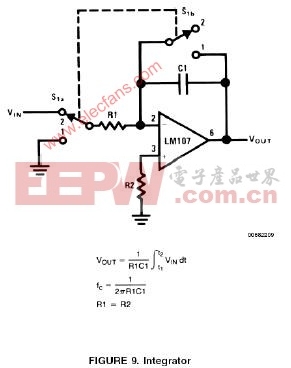
 积分器用于实现数学上的积分运算,如图9所示。在本质上,积分器可以看成是一个呈6dB/2倍频程频率特性的LPF,波特图见图10。积分器必须加入初始化电路,以给电路创造积分的初始化条件。图中S1的目的就在于此,当S1在1位置时,OP工作在单位增益(跟随器)状态。电容C1上的电荷被释放掉,使得积分初始值为0;当S1在2位置时,OP工作在积分器状态,其输出将为输入信号电压幅度对时间的积分与一个常数之积。在使用本电路时注意两点:OP在单位增益状态下应能稳定,R1和R2的阻值必须相等,以减小输入偏置电流所带来的误差。
评论