简单低通滤波器:Simple Low-pass Filter


简单低通滤波器:Simple Low-pass Filter
The simple low-pass filter is shown in Figure 11. This circuit has a 6 dB per octave roll-off after a closed-loop 3 dB point defined by fc. Gain below this corner frequency is defined by the ratio of R3 to R1. The circuit may be considered as an AC integrator at frequencies well above fc; however, the time domain response is that of a single RC rather than an integral. R2 should be chosen equal to the parallel combination of R1 and R3 to minimize errors due to bias current. The amplifier should be compensated for unity-gain or an internally compensated amplifier can be used. A gain frequency plot of circuit response is shown in Figure 12 to illustrate the difference between this circuit and the true integrator.
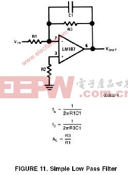
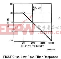
简单低通滤波器的电路如图11。本电路在闭环3dB转折点为fc,对高于fc的信号有6dB/2倍频程的衰减。低于fc频率的信号的增益由R3/R1决定,在输入信号频率远大于fc的情况下,电路可以看成是对交流信号的积分器;可以认为,在此时,从时域响应上看,比起积分来说,RC(的时间延迟特性)更明显。R2的阻值应选为R1和R3的并联阻值,以减小输入偏置电流带来的误差。在这里可以选择带内部频率补偿的OP或者在外部对单位增益的频率特性进行补偿。电路的增益波特图见图12,本图说明了LPF和真正的积分器之间在频率特性上的区别。
评论