
可调参考电压源:Adjustable Voltage Ref

可调参考电压源:Adjustable Voltage References
Adjustable voltage reference circuits are shown in Figures 19, 20, 21, 22. The two circuits shown have different areas of applicability. The basic difference between the two is that Figures 19, 20 illustrate a voltage source which provides a voltage greater than the reference diode while Figures 21, 22 illustrates a voltage source which provides a voltage lower than the reference diode. The figures show both positive and negative voltage sources.
High precision extended temperature applications of the circuit of Figures 19, 20 require that the range of adjustment of VOUT be restricted. When this is done, R1 may be chosen to provide optimum zener current for minimum zener T.C. Since IZ is not a function of V+, reference T.C. will be independent of V+.
The circuit of Figures 21, 22 are suited for high precision extended temperature service if V+ is reasonably constant since IZ is dependent on V+. R1, R2, R3, and R4 are chosen to provide the proper IZ for minimum T.C. and to minimize errors due to Ibias.
The circuits shown should both be compensated for unity-gain operation or, if large capacitive loads are expected, should be overcompensated. Output noise may be reduced in both circuits by bypassing the amplifier input.
The circuits shown employ a single power supply, this requires that common mode range be considered in choosing an amplifier for these applications. If the common mode range requirements are in excess of the capability of the amplifier, two power supplies may be used. The LH101 may be used with a single power supply since the common mode range is from V+ to within approximately 2 volts of V-.
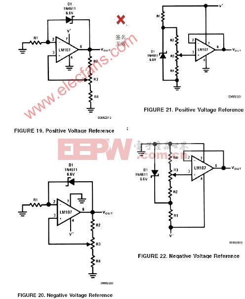
可调电压参考源的电路示于图19、20、21、22中。图中的两种电路形式有着不同的应用范围,最基本的区别在于,图19和20所示的电路可以提供大于电路中所使用的稳压二极管稳定电压的输出电压,而图21和22中的电路的输出电压小于稳压管的稳定电压。在每种形式的电路中,又分别给出了正电压和负电压输出的应用电路。
由于温度因素会影响精度,图19、20中电路的输出电压范围不能太宽。另外,由于Iz(流过稳压管的电流)与V+无关(仅取决于R1), R1的取值应该尽量使得稳压管的击穿电流大小合适,借此来减小其温度特性的影响。
图21、22中的电路适合于要求在宽温度范围内取得较好精度的情况下使用,由于Iz和V+有关,这种电路要求V+相对稳定。R1、2、3、4应该适当选择,以给稳压管提供适当的击穿电流和减小其温度特性的影响。
以上电路中的OP必须对单位增益做频率补偿,如果负载呈较大的容性,则可能需要做过补偿。如果想减小输出噪声,可以在上述电路的输入端采取旁路措施。
图中的电源采用单电源供电,这就对OP的共模输入范围的选择提出了要求,如果所要求的输入电压范围超过共模输入范围,则应该使用双电源供电。LH101的共模电压范围达V+到V-之上2V,可以在单电源的情况下使用。

评论