
自动跟踪对称电源:Tracking Regulated Po

自动跟踪对称电源:Tracking Regulated Power Supply
A tracking regulated power supply is shown in Figure 29. This supply is very suitable for powering an operational amplifier system since positive and negative voltages track, eliminating common mode signals originating in the supply voltage. In addition, only one voltage reference and a minimum number of passive components are required.
Power supply operation may be understood by considering first the positive regulator. The positive regulator compares the voltage at the wiper of R4 to the voltage reference, D2. The difference between these two voltages is the input voltage for the amplifier and since R3, R4, and R5 form a negative feedback loop, the amplifier output voltage changes in such a way as to minimize this difference. The voltage reference current is supplied from the amplifier output to increase power supply line regulation. This allows the regulator to operate from supplies with large ripple voltages. Regulating the reference current in this way requires a separate source of current for supply start-up. Resistor R1 and diode D1 provide this start-up current. D1 decouples the reference string from the amplifier output during start-up and R1 supplies the start-up current from the unregulated positive supply. After start-up, the low amplifier output impedance reduces reference current variations due to the current through R1.
The negative regulator is simply a unity-gain inverter withinput resistor, R6, and feedback resistor, R7.
The amplifiers must be compensated for unity-gain operation. The power supply may be modulated by injecting current into the wiper of R4. In this case, the output voltage variations will be equal and opposite at the positive and negative outputs.
The power supply voltage may be controlled by replacing D1, D2, R1 and R2 with a variable voltage reference.
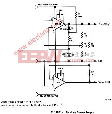
图29的电路是一个输出对称的稳压电源,它非常适合给OP供电,这是因为其正负电源电压是对称的,所以电源的共模干扰可以被抑制掉。此外,这个电路比较简洁,仅使用了一个基准电压源和很少的无源器件。
下面从正电源整流部分入手来介绍本电路的原理。正电源整流部分的OP对从电位器R4取出的电压和稳压管D2给出的参考电压进行比较,这两个电压的差值构成OP的输入电压;R3、R4、R5构成了OP的负反馈路径,因此OP的输出变化趋势会使得输入的差值尽量减小;基准电压源的电流由放大器的输出端提供,这样可以提高对电源的线性范围,使本电路可以适应纹波较大的供电电源。这样一种调节基准电压源的电流的方法需要一个单独的电流源来提供初始启动电流,电阻R1和二极管D1就起到这个作用:D1用于在启动时将启动电路和OP的输出端隔离开,而输入电源会经R1为D1提供启动电流。完成启动后,放大器很低的输出阻抗将会降低因流经R1的电流不足以影响稳压管上的电压稳定性。
负电源整流部分就是一个简单的单位增益反相器,输入电阻是R6,反馈电阻是R7。
图中所用OP必须进行单位增益稳定的补偿。如果在电位器R4的抽头处注入外接信号,就可以实现供电电源调制。这时,输出正负电压始终对称,变化量相等。
将D1、D2、R1和R2换成一个可变参考电压源,本电路就变成了一个可控电源。

评论