逻辑探针电路图,Logic Probe


逻辑探针电路图,Logic Probe
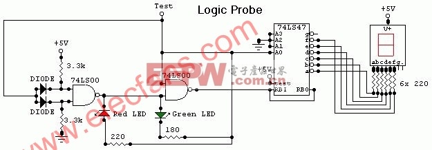
This circuit is a Logic Probe. It indicates the logic state of the node of any TTL logic circuit. To do that, we have to supply the probe with the same power of the circuit that we want to analyse: same Vcc and same GND. To check the logic level, we must connect the "Test" wire of the probe to the desired node of the circuit that we want to check.
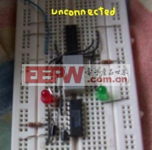
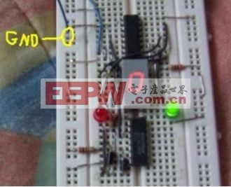
If the level is Low, the probe will display a "zero" (0) and only the green LED will be lighted. If the level is High, the probe will display a "one" (1) and only the red LED will be lighted. If the level is Impedance, the probe will display a nothing and no LED will be lighted. The logic level is "Low" when the "Test" wire is connected to the ground of the circuit (the voltage is between 0V and 2V). The logic level is "Impedance" when the "Test" wire is unconnected (it has no voltage or the voltage is between 2V and 3V). The logic level is "High" when the "Test" wire is connected to the positive supply of the circuit (the voltage is between 3V and 5V).
评论