心型闪烁灯电路


心型闪烁灯电路
Buyingagiftforsomeonespecialoralovedonecansometimesbedifficultorexpensive.Theflashingheartistheanswer.Itiseasytobuildandeventheinexperiencedhobbyistshouldbeabletobuildit.Theestimatedcostforthecircuitis$25ifallthepartsarepurchasednew.WithTheFlashingHeart,youcangetyourmessageacrossinbrightlights.CircuitDescriptionTheCircuitDiagramisshowninFigure1.Itconsistsofa4047low-powermonostable/astablemultivibrator,IC1,usedintheastablemodetoprovidethetimingpulsestocontroltheflashrateoftheLEDs.Toaccomplishtheastablemode,pins4,5,6,and14areconnectedto+12VDCandpins7,8,9,and12areconnectedtoground.Pins1and3areconnectedtoC2andpins2and3areconnectedtopotentiometerR9.AfixedvalueresistorcanbeusedinplaceofthepotentiometerR9,iftheflashratedoesnotneedtobeadjusted.ThesethreepinsmakeuptheR-Ctimingcircuit.Theoutputpulsesfromthe4047aretakenfrompins10,11,and13.Pin10istheQoutputandpin11istheQ-notoutput.ThesetwopinsareonnectedtoR6andR7respectively.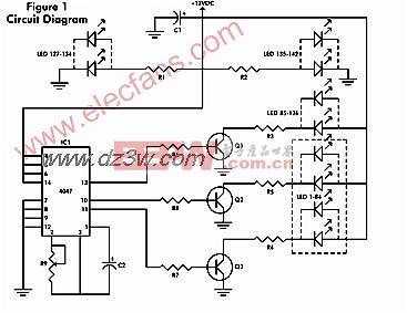
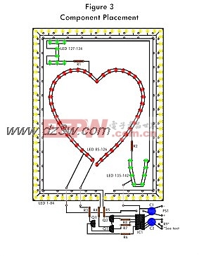
ThecollectorsofQ2andQ3areconnectedtoR4andR5respectively,whichareconnectedtothecathodesoftheYellowLEDs.Pin13istheoscillatoroutputandisconnectedtoR8,whichisconnectedtothebaseofQ1.ThecollectorofQ1isconnectedtoR3,whichisconnectedtothecathodesoftheRedLED's.Theemittersofthethreetransistorsareconnectedtoground.TheGreenLEDsareconnectedtoR1andR2,whichareconnectedto+12VDC.ResistorsR1-R8arecurrentlimitingresistorsandthecorrectwattagefortheseresistorsshouldbeusedtopreventexcessiveheat.TheresistivevaluesmaybechangedtovarythebrightnessoftheLEDs.ThecircuitispoweredbyPS1,awalltransformer,whichisconnectedtoafiltercapacitorC1.Itmustbebetween10to15VDCandatleast500mA.ConstructionProbablythemostdifficultpartofthisprojectismakingtheprintedcircuitboard,Figure2.Theboardusedintheprototypetookseveralhourstomakeusingdrytransfers.Usingadifferenttechnique,suchasphotoresist,maybefasterfortheexperiencedhobbyist.Oncetheboardisetchedanddrilled,thejumperwiresshouldbeplacedontheboardandsoldered,asshownonFigure3.Nextthe84YellowLEDsshouldbeplacedaroundtheborderoftheboard,followedbythe42RedLEDsthatmakeuptheheartandthenthe16GreenLEDsthatmakeupthelettersIandU.ResistorsR1-R9andcapacitorsC1andC2shouldbeplacedontheboardnextandthenthepowersupply,PS1.SocketswereusedintheprototypefortheI.C.andtransistors.AsocketfortheI.C.isrequired,butthesocketsforthetransistorsarenot.SpecialcareshouldbetakenwhenhandlingtheCMOSI.C.,asastaticdischargewilldestroyit.Whenyouarefinishedsoldering,checktheboardoverformistakes.Ifeverythinglooksokay,applypower.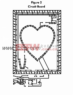
OperationOncepowerhasbeenappliedtothecircuit,theRedLEDsshouldallbeflashingonandofftogether.TheYellowLEDsshouldbeflashingonandoff,butonlyeveryotherYellowLEDshouldbeonatonetime.TheGreenLEDswillstayonatalltimes.TheflashratecanbeadjustedbyturningR9.ConnectionsforafixedvalueresistorforR9areprovidedontheboardlayoutifpreferred.Todressuptheproject,afavoritephotographcanbeplacedintheheart,andaframecanbemadetofitthecircuitboard.PartsListResistorsR1,R2-470ohm,1/2-wattR3-R5-100ohm,3-wattR6-R8-1000ohm,1.4-wattR9-5000ohmpotentiometerCapacitorsC1,C2-100uF,16volts,electrolyticradialSemiconductorsIC1-4047,lowpowermonostable/astablemultivibratorQ1-Q3-2n3643NPNtransistororequivalentDiodesLED1-LED84-yellowlight-emittingdiodeLED85-LED126-redlight-emittingdiodeLED127-LED142-greenlight-emittingdiodeOthercomponentsPS1-12VDC@500mAwalltransformerMiscellaneous:Jumperwire,solder,printedcircuitboard,drillandbits,14pinI.C.socket,andaframeorcase.
评论