Cirrus CS53L30高性能低功耗四路音频ADC评估方案
Cirrus公司的CS53L30是高性能低功耗四模数转换器(ADC),0dB增益时的动态范围91dB,THD+N为-84dB,四路全差分输入和模拟输入,-6到12d可编增益放大器,主要用于语音识别系统, 录音机,摄影机,数码相机以及高挡耳机和电话系统.本文介绍了CS53L30主要特性,框图,多种应用电路以及评估板CDB53L30主要特性,框图,电路图,PCB装配图和PCB设计图.
The CS53L30 is a high-performance, low-power, quad-channel ADC. It is designed for use in multiple-mic applicationswhile consuming minimal board space and power.
The flexible ADC inputs can accommodate four channels of analog mic or line-input data in differential, pseudodifferential,or single-ended mode, or four channels of digital mic data. The analog input path includes a +10- to +20-dB boost and a–6- to +12-dB PGA. Digital mic data bypasses the analog gain circuits and is fed directly to the decimators.
Four mic bias generators are integrated into the device. The device also includes two digital mic serial clock outputs.
The CS53L30 includes several digital signal processing features such as high-pass filters, noise gate, and volume control.The device can output its four channels of audio data over two I2S ports or a single TDM port. Additionally, up to fourCS53L30s can be used to output up to 16 channels of data over a single TDM line. This is done by setting the appropriateframe slots for each device, and each device then alternates between outputting data and setting the output pin to highimpedance.
The CS53L30 can operate as a serial port clock master or slave. In Master Mode, clock dividers are used to generate theinternal master clock and audio clocks from either the 6-/12-MHz, 6.144-/12.288-MHz, 5.6448-/11.2896-MHz, or 19.2-MHzmaster clock.
The device is powered from VA, a 1.8-V nominal supply and VP, a typical battery supply. An internal LDO on the VA supplypowers the device’s digital core. The VP supply powers the mic bias generators and the AFE.
The CS53L30 is controlled by an I2C control port. A reset pin is also included. The device is available in a 30-ball 0.4-mmpitch WLCSP package and 32-pin 5 x 5-mm QFN package.
CS53L30主要特性:
Analog Input and ADC Features
91-dB dynamic range (A-weighted) @ 0-dB gain
–84-dB THD+N @ 0-dB gain
Four fully differential inputs: Four analog mic/line inputs
Four analog programmable gain amplifiers
–6 to +12 dB, in 0.5-dB steps
+10 or +20 dB boost for mic input
Four mic bias generators
MUTE pin for quick mic mute and programmable quickpower down
Digital Processing Features
Volume control, mute, programmable high-pass filter,noise gate
Two digital mic (DMIC) interfaces
Digital Output Features
Two DMIC SCLK generators
Four-channel I2S output or TDM output. Four CS53L30scan be used to output 16 channels of 24-bit 16-kHzsample rate data on a single TDM line.
System Features
Native (no PLL required) support for 6-/12-MHz, 6.144-/12.288-MHz, 5.6448-/11.2896-MHz, or 19.2-MHz masterclock rates and 8- to 48-kHz audio sample rates
Master or Slave Mode. Clock dividers can be used togenerate common audio clocks from single-master clockinput.
Low power consumption
Less than 4.5-mW stereo (16 kHz) analog mic record
Less than 2.5-mW mono (8 kHz) analog mic record
Selectable mic bias and digital interface logic voltages
High-speed (400-kHz) I²C control port
Available in 30-ball WLCSP and 32-pin QFN
CS53L30应用:
Voice-recognition systems
Advanced headsets and telephony systems
Voice recorders
Digital cameras and video cameras

图1.CS53L30框图

图2.CS53L30典型连接图:模拟麦克风连接
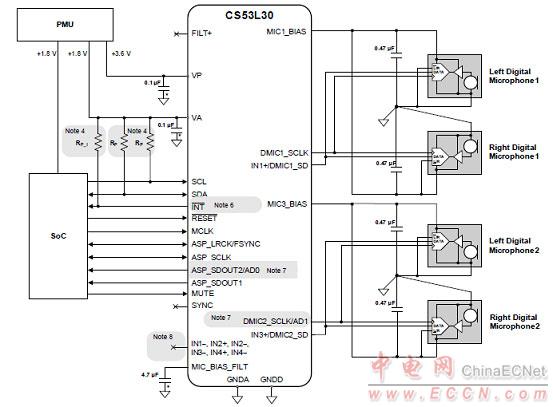
图3.CS53L30典型连接图:数字麦克风连接
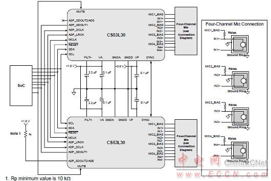
图4.双CS53L30八个麦克风电路图
评估板CDB53L30
The CDB53L30 evaluation board is a convenient platform for evaluating the CS53L30 low-power, quad-channelmicrophone ADC with TDM output. It supports multiple power supply and signal I/O configurations, including the option toconnect directly to the CS53L30 from an external system such as a host processor (while bypassing the onboard controlcircuitry). The CDB53L30 has two CS53L30 devices, providing the ability to evaluate the multichip synchronizationprotocol. To evaluate the synchronization protocol using four devices, two CDB53L30s can be linked using the SYNC I/Oheader. The CDB53L30 also serves as the component and layout reference for the CS53L30.
The CDB53L30 board is a dedicated platform for testingand evaluating the CS53L30, a low-power, quad-channelmicrophone ADC with TDM output.
To allow comprehensive testing of CS53L30 features andperformance, extensive software-configurable options areavailable on the CDB53L30.
Software options, such as register settings for theCS53L30, are configured with the FlexGUI software, whichcommunicates with the CDB53L30 via USB from aWindows®-compatible computer. In addition, digital I/Oheaders on the CDB53L30 allow external control signals(from a host processor, for example) to configure andinterface with the CS53L30 directly without the use ofFlexGUI.
The CDB53L30 also serves as the component and layoutreference for the CS53L30.
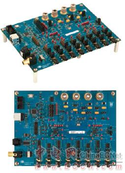
图5.评估板CDB53L30外形图
评估板CDB53L30主要特性:
• Analog or digital Inputs
— Analog microphone or line inputs via TRS 1/8” jacks
— Digital microphone inputs via stake headers
• Two CS53L30 devices support up to eight channels ofphase-aligned audio
• Onboard master clock generator
• S/PDIF transmitter interface via RCA and optical jacks
• External digital I/O via stake headers
— Serial audio port I/O
— Control signal I/O
— External I²C™ control port I/O
• Flexible power-supply configuration
— USB or external power supply
• FlexGUI software control
— Windows® compatible
— Predefined and user-configurable scripts
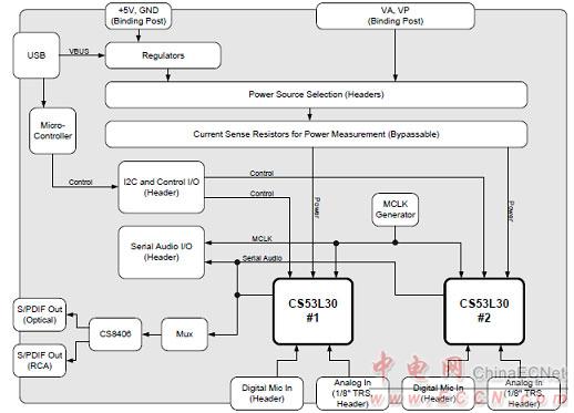
图6.评估板CDB53L30框图

图7.评估板CDB53L30电路图(1):CS53L30
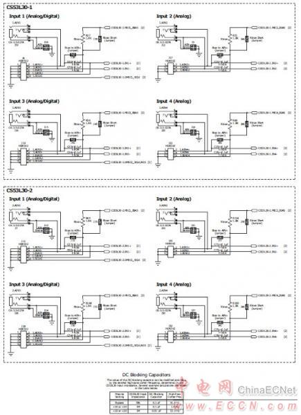
图8.评估板CDB53L30电路图(2):输入
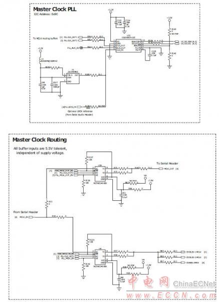
图9.评估板CDB53L30电路图(3):主时钟PLL和路由缓冲器
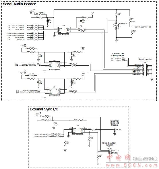
图10.评估板CDB53L30电路图(4):串行音频插头,同步I/O
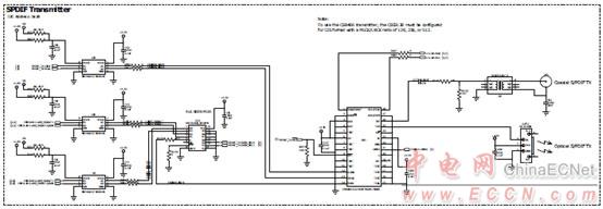
图11.评估板CDB53L30电路图(5):S/PDIF变压器
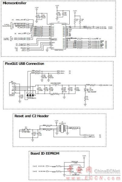
图12.评估板CDB53L30电路图(6):MCU
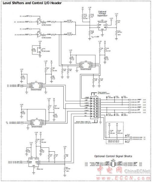
图13.评估板CDB53L30电路图(7):电平转换,控制I/O插头
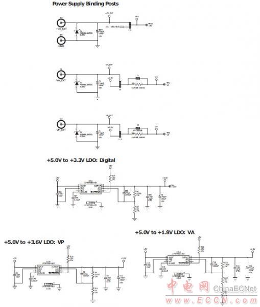
图14.评估板CDB53L30电路图(8):电源
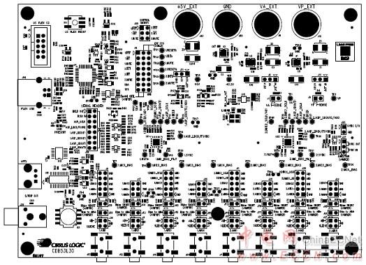
图15.评估板CDB53L30 PCB装配图(顶层)
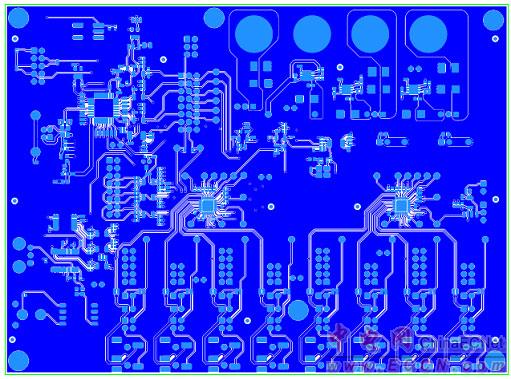
图16.评估板CDB53L30 PCB设计图(层1)
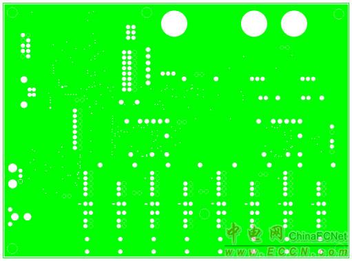
图17.评估板CDB53L30 PCB设计图(层2-地)
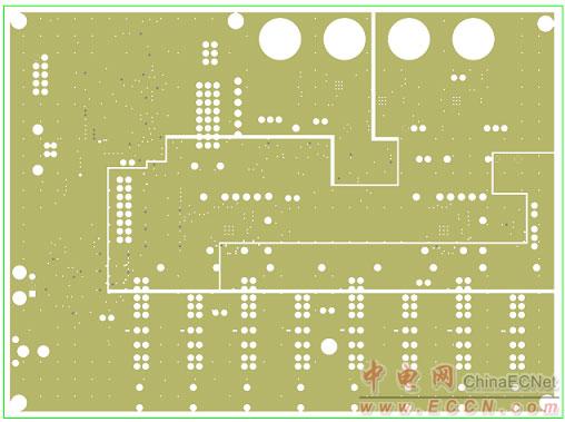
图18.评估板CDB53L30 PCB设计图(层3-3.3V,1.8V,VP)
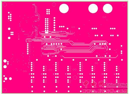
图19.评估板CDB53L30 PCB设计图(层4-信号)
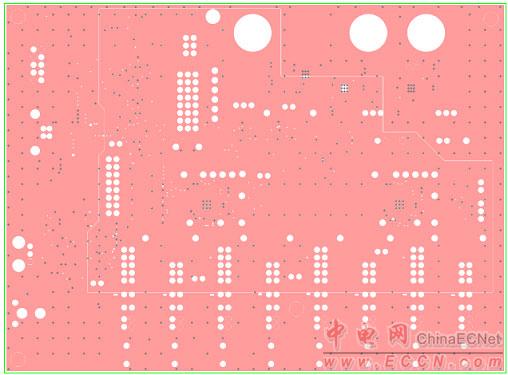
图20.评估板CDB53L30 PCB设计图(层5-VA)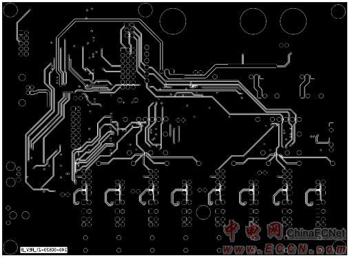
图21.评估板CDB53L30 PCB设计图(层6-信号底层)



评论