Crystal controlled 147.460 MHz


Crystal controlled 147.460 MHz FM transmitter
The XFM1 transmitter is a crystal controlled tone modulated FM transmitter designed for model rockets but suitable for wildlife, balloons and many other applications requiring a small, frequency stable FM transmitter. Use this transmitter with a scanner or 2 meter amateur radio receiver. Transmitter ground range is approximately 400 yards (5 feet above ground) . Field tests were done with a ICOM IC-W32A transceiver with 0.16 micro volts of receiver sensitivity through the standard 8 inch antenna. Air to ground transmissions can improve range significantly as will a directional high gain antenna or a more sensitive receiver.General Specifications:
Frequency: 147.455 to 147.460
Mode: FM
Size: 2 .75 "x 0.5"
Weight: 8 grams (.3 oz) including battery
Range (ground): 400 yards with counterpoise
Frequency control: Crystal
Battery life: 3 days (two CR1632 batteries in series)
Receiver Type/requirements: FM, 144.455 - 147.460 MHz., 0.16microvolts sensitivity or better
Receiver Antenna: directional antenna recommended but not required.
Other: Knowledge of radio direction findingTRANSMITTER
The transmitter is a crystal controlled 147.460 MHz FM transmitter. The transmitter is tone modulated by a 12F675 microprocessor approximately every two seconds. A Morse code call sign ID is transmitted approximately every 30 seconds. If a call sign has not been specified it will transmit “XFM1”. The transmitter is turned off between tone bursts which greatly extends the battery life. The circuit is designed to use a low cost “computer crystal” 49.39 Mhz (3rd over tone), However, custom crystals can be used if other frequencies are desired. If other frequencies are desired a 3rd overtone series crystal can be ordered from a crystal manufacture. Microprocessor
The transmitter is controlled by a program running on a PIC12F675 micro-controller. It generates the "beep" tones approximately every 1 to 2 seconds an a station ID every 16 "beeps". If no call sign is designated it transmits "XFM1".
The source code is available at www.jbgizmo.com .Power Supply
The transmitter is powered by two (2) 3 volt lithium “button” batteries type BR1632 or CR1632. Average battery life is 3 days of continuous operation.AntennaThe transmitter antenna is 12 inches of 20 to 24 gauge common "hook-up" wire. The range of the transmitter can be doubled by attaching a wire (counterpoise) of the same length as the antenna from the positive supply extending in the opposite direction of the antenna. Both the counterpoise and the transmitter antenna can be coiled on a 1/2 to 3/4 inch diameter to shorten the length of the antenna and to allow storage inside a payload compartment. Coiling the antenna does shorten the range of the transmission.A method that works well in most cases is to suspend the module from the nose cone by the coiled counterpoise, and extend the transmitter antenna into the payload compartment or out the bottom of the payload compartment and along side the fuselage. The coiled counter poise provides a shock absorbing function during lift-off.Construction:Construction of the telemetry transmitter is straightforward. NOTE: Be aware that the small size of the circuit requires that GREAT CARE be taken to prevent solder bridges when soldering. Use a 20 to 40 watt soldering iron with a pencil sharp point; trim all leads after soldering and check each solder joint with a magnifying glass for bridges and solid connection.
Please refer to the "Component Side View" illustration when installing parts. All components are installed on the blank side of the board (not the foil side).When installing components bend the leads to match the hole spacing. Push the leads through the holes at the proper location being careful of polarity on the IC and transistor.Solder the leads on the foil side of the board being careful not to produce solder bridges. Trim all excess leads immediately after each component installation
Note: There are 8 solider pads that are not drilled (have no holes) . These pads are for use by anyone that would like to extend the design of the transmitter through their own experimentation and programming. These pads provide easy access to the other pins on the PIC chip and can be programmed for analog inputs or Digital I/O by the knowledgeable experimenter. If you are not interested in experimenting with the programming you can use the circuit as-is in the basic tracking mode.
NOTE: In some circuits the transmitter will not turn off after "beeps" or after completing the call ID. This condition can be corrected by adding a 15 pF capacitor at the location marked on the parts placement diagram( parallel to L1 and C2). Holes are provided for this installation.
- If the crystal is not already installed on the printed circuit board (PCB), solider the crystal in place. If the crystal is not installed then carefully straighten the leads to match the holes in the PCB. The leads should be perpendicular to the base when properly bent. Bending the leads more than twice will cause the leads to break and the crystal will need to be replaced.
- Solider the 8 pin DIP socket in the location marked as “IC1”. Position the notch end of the socket towards the battery end of the PCB.
- Solder R1, 10K ohm resistor (brown/black/orange) resistor in the place shown.
- Solder R2, 100K ohm (brown/black/yellow) resistor in the place shown
- Solder C1, .001 microfarad capacitor in place (may be marked as 102)
- Solder C2, the 47 picofarad capacitor in place (may be marked as 47)
- Solder C3, 15 picofarad capacitor in place (may be marked as 150 or 15)
- Using one of the trimmed off leads from the previous component installations solder a jumper at location marked J1.
- Solder L1, 0.63 microhenry coil in place
- Measure 3.25” of 22 gage magnet wire. Using a knife carefully scrape the lacquer from the ends of the coil for about 1/2 inch. Next construct the coil (L2) by close winding 4 turns of the magnet wire on the shaft of a 1/8" drill bit shaft (or similar size form) and then slide the coil off of the drill bit shaft or form. The coils should be tightly wound. Solder this coil in place at location L2 making sure that the solder adheres to the bare portion of the magnet wire..
- Remove the emitter from the NTE108 transistor (if not already done)
- Solder Q2, NTE108 transistor, in the place indicated. Note the orientation of the case on the diagram.
- Solder Q1, NTE107 transistor, in the place indicated. Note the orientation of the case on the diagram.
- The battery holder consist of two jumpers, made from the trimmed off resistor leads, soldered flat against the component side of the circuit board. These two jumpers form the negative battery terminal. The positive battery terminal is made from a small metal paper clip and arches over the top of the batteries. The depth of the arch should just be high enough to allow two 3-volt lithium coin batteries to fit under it. After the “hold down wire” is soldered in place the top portion can be crimped as shown in the “Component Side View” to increase the tightness of the holder.
Solder the two negative battery contact jumpers as shown (using leads from the previous component installations ).
Before Soldering the “hold down wire” remove 1/4 inch of insulation from one end of the antenna wire and the counterpoise wire and slide them over the vertical portion of the hold down wire (see diagram). This will form an insulating sleeve and keep the bottom battery positive terminal from touching the metal. Then solder the hold down wire in place as shown.- Install the antenna. Remove 1/2 inch of the insulation from one end of a 12.5” wire and feed through the hole in the circuit board as indicated. Wrap the circuit board end of the antenna around the edge of the circuit board and twist it around itself on top of the circuit board. Solder the antenna to the circuit board and where it is twisted together.
- Install the counterpoise in the same manner as the antenna wire from the location indicated (opposite end of PCB from antenna).
- Install the IC1 (PIC12F675) into the 8 pin DIP socket. Insure that the notched end of the IC is facing the battery end of the board.
- Install the batteries by stacking two BR1632 or CR1632 batteries under the battery “hold down wire” with the positive side facing up. When you are operating the transmitter on a mission you will need to secure the batteries with several wraps of tape to insure that the batteries do not jar lose during launch or recovery.
Testing:
- Install the batteries. Two 1632 batteries stacked with positive (+) side up. Confirm operation of transmitter. Note that due to variations in crystal frequency the actual frequency of the transmitter will be in the range of 147.455 and 147.560 Mhz.
- Further secure the battery by securing it to the PCB with several wraps of electrician’s tape.
- Verify operation.
- Stand in the middle of an open short grassy area. Swing the transmitter by the antenna and throw it in the air (straight up).
- Verify that the transmitter functions throughout the flight and after bouncing on the ground.
- If transmitter still functions it is ready for use in model rocket tracking.
- The two most common problems encountered in the test are.
*Poor battery connections. Make sure the battery clip is slightly bowed and firmly against the
battery terminal.
*Antenna wire not soldered to the circuit board adequately (cold solder joint).
Coating the circuitIf the transmitter is to be exposed to the environment or hot ejection gases it needs to be coated with a protective coating of polyurethane. The circuit board and all the components with the exception of the battery and the battery terminal should be coated with 2 coats of polyurethane to protect the circuit from environmental factors.OperationHave someone hide the transmitter and practice finding it before you use it on a mission. Note: there are several good references for radio direction finding (RDF) that you may want to read. The ARRL Handbook has a chapter on RDF and can be found in most public libraries. Transmitter Hunting, by Joseph Moell, K0OV and Thomas Curlee, WB6UZZ is also a good book on the subject. Both books can be bought from Amazon.com.Radio direction finding is best accomplished by using a receiver with a directional antenna like a “beam” or “Yagi“antenna, however a monopole antenna can be used by employing the “Body-Fade” method. Instructions for building two good inexpensive RDF Yagi type antennas can be found at http://www.clarc.org/Articles/uhf.htm and http://home.att.net/~jleggio/projects/rdf/tape_bm.htm . The first one was designed by Kent Britain, WA5VJB and the second one was designed by Joe Leggio, WB2HOL. You might also need an RF attenuator for when you get close to the transmitter (check Joe’s attenuator plans at http://home.att.net/~jleggio/projects/rdf/p_atten.htm)Body Fade:If you use your body to shield the receiver’s monopole antenna a cardioid sensitivity pattern (see picture) is achieved. The peak null position is approximately 180 degrees opposite the transmitter location.(Note that the patterns are not always as shown. They can vary depending on the antenna, the way it is being held and objects in the area that may reflect the signal). operator should take a reading by holding the receiver close to their stomach The antenna should extend vertically and be about 6 inches in front of the body. Turn slowly listening for the strongest signal (loudest beeping) or highest reading on the “S“ meter. Move in the direction of the strongest signal (opposite the direction of the weakest signal). Periodically stop and take another reading, adjust the course and continue to work towards the transmitter. Since the “null” point is much narrower than the maximum signal point it may be easier to use the “null” point to establish the most accurate direction to the transmitter. With a little practice a person can become quite efficient in locating the transmitter although the path taken will be somewhat zigzagged.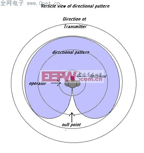

Directional Beam antenna:A “beam” or “Yagi” antenna is probably the simplest and best all around choice for a directional antenna. A simple 3 element antenna can be built for about 10.00 using common materials. The sensitivity pattern shown below is when both the transmitter and receiving antenna is polarized vertically (the elements are pointing up and down). If the antenna of the transmitter are not vertical then the pattern will be different unless the receiving antenna is orientated to match the transmitter antenna. Since the transmitter antenna’s orientation is not always known some experimentation must be done with the receiving antenna. (Note that the patterns are not always as shown. They can vary depending on the antenna, the way it is being held and objects in the area that may reflect the signal).Practice helps a lot!

Receivers
To achieve adequate performance you will need a receiver with at least 0.16 micro volts of sensitivity. Most 2-meter Amateur (ham) radios are at least this sensitivity. Scanners may or may not be sensitivity enough.
Component Side View
reversed foil side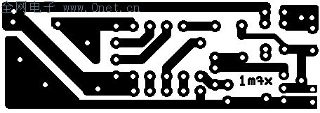
2" x 0.65"
foil side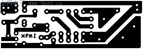
Transmitter parts
Resistors | Value | Part number | Supplier | Comments |
R1 | 10K 1/8 watt | 299-10K | Mouser | |
R2 | 100K 1/8 watt | 299-100K | Mouser | |
Capacitors | ||||
C1 | .001uF | 21RX510 | Mouser | |
C2 | 22pF | 21RD722 | Mouser | |
C3 | 15pF | 80-C315C150J1G | Mouser | two C3 (15pF caps) may be needed (see text) |
Semiconductors | ||||
Q1 | NTE107 | 526-NTE107 | Mouser | |
Q2 | NTE108 | 526-NTE108 | Mouser | |
Crystal | ||||
xtal | 147.460 | 815-ABLS-49.152-B2 | Mouser | 49.152MHZ 3rd overtone crystal |
Inductors | ||||
L1 | 0.68 uH | 434-22-R68 | Mouser | |
L2 | 4 turns #22 magnet wire tightly wound on 1/8"dia. | 278-1345B | Radio Shack | Enamel-coated magnet wire |
Miscellaneous | ||||
Battery | CR1632 or BR1632 | 658-BR1632 | Mouser | |
PCB | See foil pattern | |||
antenna & Counterpoise | 12 inch | #20 to #24 solid conductor wire | Just about any type of “hook-up” or phone wire | |
J1 | Jumper wire | Use trimmed off lead | ||
| source code | tele147_1.asm |
评论