
0.7~24V连续可调限流电源-----0.7 ~ 24V adjustable current-limiting power supply

0.7~24V连续可调限流电源
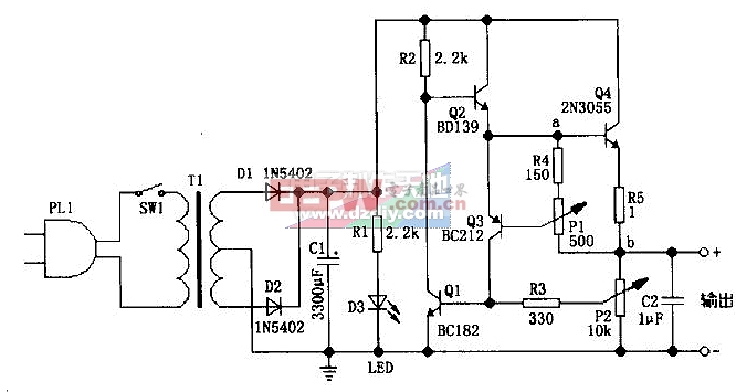
图中的电路可以实现输出电压0.7~24V连续可调,并且可以实现50mA~2A可调的最大输出电流限制。
P1用来设置输出电流最大限值,调整它可以在相应的输出电压时,给出50mA~2A的电流限制。P1设置输出电流最大限值的原理如下:从图中可以看出,输出电流主要来自Q4的发射极,这样,当输出电流增大,电路中a、b点间的电压也跟着增大,这时,a点(即Q3的e极)和Q3的b极间的电压也增大,而Q3的e、b极间电压不可能超过0.7V,当Q3的e、b极间电压增大时,Q3的e极会分流走流往Q4的b极的电流,这样,就限制了a、b点间电压的增大,从而实现最大输出电流限制的目的。
P2用做输出电压调节。当输出电压增大,Q1的e、b极间电压也增大,这导致Q1分流走流往Q2的b极的电流,Q2导通电流下降后,不难看出Q4的导通电流也下降,从而使输出电压下降。当输出电压减小时,原理类似。
P2建议用对数型的电位器,这样输出电压的可调性和线性会更好些。
电源变压器的输出电压和容量应根据你所需要的输出电压和电流来选区。最佳的方案是:变压器次级电压为36、40、48V或带中间抽头的50、75、80V,容量为100VA。
电容C1可以从2200~6800uF/35~50V之间选择。
电路中,BC182为50V/100mA/NPN三极管,BD139为80V/1.5A/NPN三极管,BC212为50v/100mA/PNP三极管,2N3055为60V/15A/NPN三极管。Q4必须使用散热器,另外它可以使用TIP3055代替。
google translate:
0.7 ~ 24V continuously adjustable current limiting power supply
The circuit diagram can be achieved output voltage 0.7 ~ 24V continuously adjustable, and can be adjusted to achieve 50mA ~ 2A maximum output current limit.
P1 is used to set the maximum output current limit, you can adjust the output voltage in the corresponding given 50mA ~ 2A current limit. P1 to set the maximum output current limit of the principle is as follows: As can be seen from the diagram, mainly from the Q4 output current emitter, so that when the output current increases, the circuit in a, b points, also followed the voltage between the increase Then, a point (that is Q3 of e pole) and Q3 of the b pole voltage between the increase and Q3 of the e, b can not exceed the voltage between 0.7V, when the Q3 of e, b the voltage between electrodes increased time, Q3 e-flow to the most would be diverted away most of the current Q4 of b, so that the limits a, b point between voltage increases, the maximum output current limit in order to achieve the purpose.
P2 used as the output voltage regulation. When the output voltage increases, Q1 of the e, b the voltage between electrodes is also increased, leading to the Q2 Q1 flow diversion away the b-polar current, Q2 conduction current decreases, not difficult to see Q4 current will also decrease so that the output voltage drops. When output voltage decreases, the principle of similar.
P2 suggested logarithmic potentiometers, so the output voltage is adjustable and linear will be better.
Power transformer output voltage and capacity you need should be based on the output voltage and current to constituency. The best option is: Transformer secondary voltage 36,40,48 V or with intermediate tap 50,75,80 V, capacity of 100VA.
Capacitor C1 can be 2200 ~ 6800uF/35 ~ 50V to choose between.
Circuit, BC182 transistor for the 50V/100mA/NPN, BD139 to 80V/1.5A/NPN transistor, BC212 to 50v/100mA/PNP transistor, 2N3055 transistor to 60V/15A/NPN. Q4 must use the radiator, while it can use TIP3055 replace.
评论