
Creating a Fast Load Transient

Creating a Fast Load Transient
Abstract: A simple circuit generates fast load transients for thorough testing of power supplies. Many of Maxim's devices show a typical operating characteristic (TOC) graph with a very fast load transient. Our customers sometimes ask us how we create such fast changes in load. Although commercially available dynamic load boxes are capable of supplying transients, they do not provide the fast rise times and fall times necessary for an attractive-looking TOC.To obtain fast load transients, we combine a power MOSFET and a couple of resistors right on the PC board of the device under test (DUT). Choosing the components is relatively easy. If the output voltage is positive, an n-channel MOSFET works great. The MOSFET is connected with a resistor from the source to ground (see Figure 1). The MOSFET's gate is terminated with a 51Ω resistor to impedance-match the signal generator's output.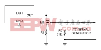 R1 = 70% × (VOUT/IOUT) And for the MOSFET: RDS(ON) = 20% × (VOUT/IOUT) If the DUT requires relatively low output currents, it can be difficult to find a MOSFET that satisfies the above criteria. In that case, increase the R1 percentage to 95% and decrease the MOSFET resistance to less than 5%.The goal of this circuit and its calculations is to dynamically trim the load current to an exact value using the MOSFET as a variable resistor. The peak load-transient current is adjusted by changing the high voltage driven into the MOSFET's gate. Using this scheme eliminates the task of adjusting the load resistor, R1, to a precise value.Note that the MOSFET is connected above the load resistor. Alternatively, the load resistor can be connected between the MOSFET's drain and the DUT output. Nonetheless, the method shown in Figure 1 works better because of the self-regulating action resulting from the degeneration of the MOSFET's transconductance.For example, assume a particular circuit has VOUT = 1.3V, IOUT = 1A, and R1 = 1Ω. Therefore, the MOSFET's VGS is initially biased so that the MOSFET acts as a 300mΩ resistor. However, due to temperature change, the MOSFET's VGS(TH) has decreased, causing the MOSFET to conduct more current than the initial condition. In turn, this additional current causes more I*R drop across R1, which decreases the MOSFET's VGS. Thus, the MOSFET's current is reduced to approximately its initial value. This is a first-order correction only, but is close enough for our purposes.For TOC figures that require load transients with a DC bias current other than 0A (e.g., the MAX8654 step-down regulator), a load resistor (RLOAD) is placed at the output of the DUT. See Figures 2 and 3. The MAX8654's load transient response shows a DC bias current at approximately 2A (MOSFET M1 off). Since VOUT is regulated to 3.3V, this can be attained with a load resistor of 1.65Ω. Using six 5W 10Ω resistors in parallel should suffice.In Figure 2 IOUT rises from 2A to 3.3A (MOSFET M1 on). Assuming that the on-resistance (RDS(ON)) of M1 is relatively small to R1, choose R1 so that the parallel combination of RLOAD and R1 = 1Ω.
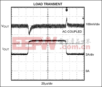 Figure 3. Load transient response setup.To achieve the best performance, keep the signal generator's duty cycle to 10% to reduce self-heating. Also, some converters are capable of supplying more than 25W, which is sufficient to cause minor injury or destroy the components if operated above 10% duty cycle.The physical location of the components is critical for best performance. Usually they have to be cobbled onto an existing PC board. Keep both the MOSFET and R1 as close to the DUT's output capacitor as possible. Make the conductors as wide and short as you can.Measurement of the DUT output should be done directly across the output capacitor. If the device is insensitive to 1000pF loading, use a 1X scope probe. The 1X probe provides the highest signal-to-noise ratio to the oscilloscope.Whatever probe is used, though, make sure to have the ground lead as close to zero length as possible. Ideally, a scope-probe jack connected directly to ground and the output works very well. Any high-speed edge to be displayed on the scope is subject to this criterion, not just transient response.
评论