
Small Antennas for 300MHz to 4

Small Antennas for 300MHz to 450MHz Transmitters
| Larry Burgess |
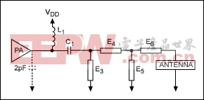
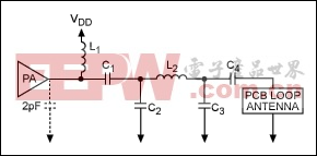
Abstract: This application note details the variety of antennas that are used in today's handheld transmitter applications, such as remote keyless entry (RKE) systems, tire pressure monitors (TPMs), garage door openers, home security sensors, or even TV remote controls. This application note discusses loop/whip, raised-strip/"paper-clip," conventional whip, helix, and patch antennas, and presents networks for matching them to Maxim's transmitters. IntroductionAntennas for transmitters that are used in remote keyless entry (RKE), tire pressure monitors (TPMs), garage door openers, home security sensors, and TV remote controls need to fit in very small packages. Because of this, almost all antennas used in these applications are electrically short (i.e., the dimensions are 0.1 wavelengths or shorter). This application note describes how these antennas are formed and gives estimates of their impedances.Antenna TypesPrinted Circuit Board Loop or Whip AntennaA printed circuit board loop or whip antenna is a circular, elliptical, square, or rectangular trace on a printed circuit board (PCB). Assuming a two-sided PCB is used for the application, the other side of the PCB underneath the antenna should be bare. No ground plane or other traces should be placed under the antenna.The input—also known as the "driven" or "feed-point" end of the antenna trace—is connected to the power amplifier (PA) either directly or through a matching network. The components in the matching network are located above a ground plane on the other side of the PCB. It is usually at the driven end that the ground plane on the opposite side of the PCB ends so that the area below the printed antenna is bare. The other end of the printed antenna is connected to the ground plane. This is usually done by ending the trace at a large area on the top layer of the PCB that is connected to the ground plane beneath with vias. However, it can also be done by connecting the end of the antenna directly to the ground plane below with a via.If the other end of the antenna is open, the antenna becomes a whip, or monopole antenna. A whip can be printed on a PCB by running a trace that is either straight or is a portion of a circle, ellipse, square, or rectangle. Figure 1 is a sketch of a PCB loop/whip antenna. A small loop with the typical dimensions of a handheld transmitter (2cm to 5cm per side) has an inductance of 30nH to 100nH and an equivalent series resistance of a few ohms. In theory, the series resistance is less than one ohm, but board losses, dielectric losses from any cover, coupling to other circuit components, and measurement tolerances can cause the resistive part to measure as high as 10Ω with a network analyzer.A small whip with the typical dimensions of a handheld transmitter has a capacitance of 1pF to 5pF and an equivalent series resistance of a few ohms. The theoretical series resistance for a small whip is about 10 times larger than the series resistance for a small loop of the same dimensions, but it is still tiny and the practical, measured resistance is about the same as with a loop antenna.Although printed antennas save money, the drawback in using them is that their characteristics depend on the manufacturing tolerances of the board material and traces. There are surface-mount antennas available with much more repeatable characteristics, and they should be considered when consistency of the antenna design is important. A small loop with the typical dimensions of a handheld transmitter (2cm to 5cm per side) has an inductance of 30nH to 100nH and an equivalent series resistance of a few ohms. In theory, the series resistance is less than one ohm, but board losses, dielectric losses from any cover, coupling to other circuit components, and measurement tolerances can cause the resistive part to measure as high as 10Ω with a network analyzer.A small whip with the typical dimensions of a handheld transmitter has a capacitance of 1pF to 5pF and an equivalent series resistance of a few ohms. The theoretical series resistance for a small whip is about 10 times larger than the series resistance for a small loop of the same dimensions, but it is still tiny and the practical, measured resistance is about the same as with a loop antenna.Although printed antennas save money, the drawback in using them is that their characteristics depend on the manufacturing tolerances of the board material and traces. There are surface-mount antennas available with much more repeatable characteristics, and they should be considered when consistency of the antenna design is important.Raised-Strip or "Paper-Clip" AntennaA raised-strip or paper-clip antenna, shown in Figure 2, is very similar to a printed loop or whip antenna. Usually, it is an external wire or flat strip of metal that connects to the PCB, rises up a few millimeters, then follows the same contour as a printed antenna. A minor advantage of this type is that the antenna is slightly removed from the other components on the PCB. The far end of the antenna can be left floating, be supported by a nonconducting standoff, or bent down and connect to the PCB. Once on the PCB, it can go to a pad that can be populated to connect to the ground plane, stay open, or connect to ground through a passive element such as an inductor or capacitor. Conventional Whip AntennaSome handheld devices have room in another direction for a conventional whip or "stub" antenna. This is usually a 2cm to 5cm wire, sometimes covered with a protective dielectric material. It can be an off-the-shelf (OTS) antenna with performance data or a "do-it-yourself" piece of metal. The OTS antennas have more repeatable impedance characteristics than some of the PCB antennas, which may be because these antennas experience more internal losses to make their resistance larger. Some of the larger OTS antennas may have impedances that are close to 50Ω with no reactance (capacitance or inductance). They may also have an internal inductor that can tune out capacitance. Figure 3 shows two stand-alone whip antennas.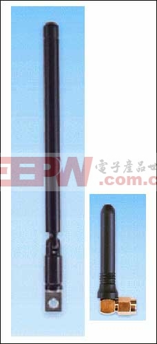 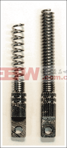 Generic Matching Network for Maxim's TransmittersFigure 5 depicts a good network for matching Maxim's transmitters to any of the antennas described above. Assigned pads can be populated by inductors or capacitors, depending on the desired antenna type. The series element, E6, or the shunt element, E5, can be used to tune out some or all of the reactance and change the equivalent resistance of the antenna. Elements E3, E4, and E5 are usually used to form a pi-network lowpass filter (LPF) to reject higher order harmonics from the PA output. If E5 is used as a tuning element for the antenna, its value can be combined with the value needed for the pi-network LPF. The inductor (L1) is required to isolate the RF from the DC supply, and the capacitor (C1) is needed to provide a DC block, but their values can also be chosen to perform another impedance transformation if needed. Most of Maxim's transmitters work at their best efficiency and power output if they are driving a resistance (real impedance) between 125Ω and 250Ω. The exception is the higher power MAX7044, which operates best with a resistance between 60Ω and 120Ω because it maintains the RF voltage swing across a smaller load resistance. MAX7044 pdf datasheet |
评论