External Temperature Sensor Calibration for the MAX16031/MAX16032 System Monitors
Abstract: The MAX16031/MAX16032 system monitors support external diode-connected transistors to sense remote temperatures. Diode-connected transistors exhibit temperature-dependent characteristics, which can be measured using a simple process. These characteristics are slightly different depending on the type of transistor; therefore, a calibration process needs to be performed before the MAX16031/MAX16032 can produce accurate temperature readings. The MAX16031/MAX16032 EEPROM-configurable system monitors are designed to monitor voltages, temperatures, and current in complex systems. These EEPROM-configurable devices allow enormous flexibility in selecting operating ranges; upper and lower limits for temperature, voltage, and current; fault output configuration; and operating modes with the capability of storing these values within the device.The MAX16031 monitors up to eight voltages, three temperatures (one internal/two external remote temperature diodes), and a single current. The MAX16032 monitors up to six voltages and two temperatures (one internal/one remote temperature diode). Each of these monitored parameters is multiplexed into the ADC and written to its respective register that can be read back through the SMBus and JTAG interfaces.Calibration parameters located in the EEPROM for the external temperature sensors must be set by the customer, as they are dependant upon the type of diode used in the application circuit. This application note provides a procedure for calibrating the external temperature sensors. A general, two-current method for measuring temperature is presented briefly, followed by the specific two-current implementation used by the MAX16031/MAX16032. Also provided is a specific calibration procedure that uses a diode-connected 2N3904 transistor as an example.Temperature Sensing ReviewAll semiconductor devices exhibit temperature dependencies. Of special interest is the IV curve of a forward-biased PN junction, which depends heavily on temperature. The following diode equation models this behavior: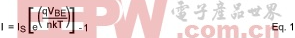 where T is the temperature measured in Kelvins, n is the diode ideality factor, k is Boltzmann's constant (1.38e-23), q is the charge of an electron (1.6e-19), VBE is the base-emitter voltage, IS is the reverse saturation current, and I is the diode current.A simple, yet accurate way to sense the temperature is to force two different currents through a diode and take the voltage difference between the base emitter voltages for each current. This cancels out the dependency on IS and makes the relationship between the base-emitter voltage difference and temperature quite linear. The following equation shows how this works for two currents, IH and IL. where T is the temperature measured in Kelvins, n is the diode ideality factor, k is Boltzmann's constant (1.38e-23), q is the charge of an electron (1.6e-19), VBE is the base-emitter voltage, IS is the reverse saturation current, and I is the diode current.A simple, yet accurate way to sense the temperature is to force two different currents through a diode and take the voltage difference between the base emitter voltages for each current. This cancels out the dependency on IS and makes the relationship between the base-emitter voltage difference and temperature quite linear. The following equation shows how this works for two currents, IH and IL. where ΔVBE is the difference in base-emitter voltages at both currents, IH is the higher forcing current, and IL is the lower forcing current. The other parameters remain the same from before. Solving for T and converting to degrees Celsius yields the following: where ΔVBE is the difference in base-emitter voltages at both currents, IH is the higher forcing current, and IL is the lower forcing current. The other parameters remain the same from before. Solving for T and converting to degrees Celsius yields the following: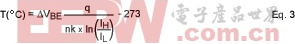 This equation shows that the temperature is directly proportional to ΔVBE with a ratio determined by physical constants, the diode ideality factor, and the ratio of the two sensing currents. This equation shows that the temperature is directly proportional to ΔVBE with a ratio determined by physical constants, the diode ideality factor, and the ratio of the two sensing currents.MAX16031/MAX16032 Temperature SensingThe MAX16031/MAX16032 measure the temperature of the external temperature diodes using the two-current technique discussed in the last section. After scaling and converting ΔVBE to a digital code, the device subtracts a fixed code representing the -273.15 degree offset. The resulting number is the temperature in degrees Celsius with a resolution of 0.5°.The temperature-sensing circuitry requires calibration to compensate for different diode ideality factors. There are two calibration values required for each external temperature sensor in the MAX16031/MAX16032: a gain and an offset.A gain value, stored in r19h[7:2] (sensor 1) and r4Fh[5:0] (sensor 2) controls the IH current (the IL current is fixed at 6µA). Table 1 shows the bit weights for each gain register bit. For example, the value 110000b corresponds with an IH of 84µA.Table 1. Gain Register Bit Weights | r19h[7:2], r4Fh[5:0] Bit | IH Value Added to 80µA (µA) | | Logic '1' | Logic '0' | | 0 | +0.25 | 0.0 | | 1 | +0.25 | 0.0 | | 2 | +0.5 | 0.0 | | 3 | +1.0 | 0.0 | | 4 | 0.0 | +2.0 | | 5 | +4.0 | 0.0 |
Table 2. Offset Register Values | r1Bh[7:5], r4Dh[6:4] Value | Offset (°C) | | 100 | +8 | | 101 | +6 | | 110 | +4 | | 111 | +2 | | 000 | 0 | | 001 | -2 | | 010 | -4 | | 011 | -6 |
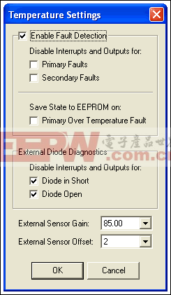 Figure 2. Current and Temperature Tab.During the calibration procedure, as well as during normal operation, it is very helpful to enable the built-in digital temperature sensor filter. In the EV kit software, choose a center frequency from the Temp sense filter time constant dropdown list located in the Miscellaneous tab. This corresponds with register r5Bh[6:4], which is described in Table 3.Table 3. Temperature Sensor Digital Filter Figure 2. Current and Temperature Tab.During the calibration procedure, as well as during normal operation, it is very helpful to enable the built-in digital temperature sensor filter. In the EV kit software, choose a center frequency from the Temp sense filter time constant dropdown list located in the Miscellaneous tab. This corresponds with register r5Bh[6:4], which is described in Table 3.Table 3. Temperature Sensor Digital Filter | r5Bh[6:4] Value | Cutoff Frequency (Hz) | | 000 | Filter Disabled | | 001 | 2.53 | | 010 | 5.06 | | 011 | 10.1 | | 100 | 20.2 | | 101 | 40.5 | | 110 | 81 | | 111 | 162 |
For best results, the sensor being calibrated should be immersed in a nonconductive fluid in a temperature-controlled bath. The example uses Fluorinert FC-77, although other fluids such as mineral oil may also work. If such equipment is not available, a commercially-available toaster oven may suffice if the sensor is attached to a metal object with a large thermal mass—this increases temperature stability during calibration. Use an accurate thermocouple with good thermal coupling to the sensor in order to measure the temperature.Use the following procedure to gather the calibration data: - Make sure the offset register is set to zero.
- Set the temperature to the low value (in this example, +25°C), allowing enough time for stabilization.
- Set the gain register to 80µA.
- Record the digital value returned by the MAX16031.
- Repeat step 4 for every possible gain register value.
- Set the temperature to the high value (in this example, +85°C), allowing enough time for stabilization.
- Repeat steps 3, 4, and 5.
Several simple calculations should be performed once the data is collected. For each temperature collected from the MAX16031, calculate the error value:| TERR = TMAX16031 - TMEASURED | Eq. 4 |
| Δ = TERR_85 - TERR_25 | Eq. 5 |
Table 4. Example Calibration Data | Gain Reg Code | Gain Value (µA) | TMAX16031 (°C) | TERR (°C) | Δ (°C) | | +25 | +85 | +25 | +85 | | 0x10 | 80 | 17.5 | 75 | -7.5 | -10 | -2.5 | | 0x12 | 80.25 | 17.5 | 75.5 | -7.5 | -9.5 | -2 | | 0x14 | 80.5 | 17.5 | 76 | -7.5 | -9 | -1.5 | | 0x16 | 80.75 | 18 | 76.5 | -7 | -8.5 | -1.5 | | 0x18 | 81 | 18.5 | 76.5 | -6.5 | -8.5 | -2 | | 0x1A | 81.25 | 18.5 | 77 | -6.5 | -8 | -1.5 | | 0x1C | 81.5 | 19 | 77.5 | -6 | -7.5 | -1.5 | | 0x1E | 81.75 | 19.5 | 78 | -5.5 | -7 | -1.5 | | 0x0 | 82 | 20 | 78.5 | -5 | -6.5 | -1.5 | | 0x2 | 82.25 | 20 | 79 | -5 | -6 | -1 | | 0x4 | 82.5 | 20.5 | 79 | -4.5 | -6 | -1.5 | | 0x6 | 82.75 | 21 | 79.5 | -4 | -5.5 | -1.5 | | 0x8 | 83 | 21 | 80 | -4 | -5 | -1 | | 0xA | 83.25 | 21.5 | 80.5 | -3.5 | -4.5 | -1 | | 0xC | 83.5 | 22 | 81 | -3 | -4 | -1 | | 0xE | 83.75 | 22.5 | 81.5 | -2.5 | -3.5 | -1 | | 0x30 | 84 | 22.5 | 82 | -2.5 | -3 | -0.5 | | 0x32 | 84.25 | 23 | 82 | -2 | -3 | -1 | | 0x34 | 84.5 | 23 | 82.5 | -2 | -2.5 | -0.5 | | 0x36 | 84.75 | 23.5 | 83 | -1.5 | -2 | -0.5 | | 0x38 | 85 | 24 | 83.5 | -1 | -1.5 | -0.5 | | 0x3A | 85.25 | 24.5 | 83.5 | -0.5 | -1.5 | -1 | | 0x3C | 85.5 | 24.5 | 84 | -0.5 | -1 | -0.5 | | 0x3E | 85.75 | 25 | 84.5 | 0 | -0.5 | -0.5 | | 0x20 | 86 | 25.5 | 85 | 0.5 | 0 | -0.5 | | 0x22 | 86.25 | 25.5 | 85 | 0.5 | 0 | -0.5 | | 0x24 | 86.5 | 26 | 85.5 | 1 | 0.5 | -0.5 | | 0x26 | 86.75 | 26.5 | 86 | 1.5 | 1 | -0.5 | | 0x28 | 87 | 26.5 | 86.5 | 1.5 | 1.5 | 0 | | 0x2A | 87.25 | 27 | 87 | 2 | 2 | 0 | | 0x2C | 87.5 | 27.5 | 87 | 2.5 | 2 | -0.5 | | 0x2E | 87.75 | 28 | 87.5 | 3 | 2.5 | -0.5 |
The values obtained for the offset and gain registers may now be loaded into the EEPROM configuration registers of the MAX16031 monitor used in the application circuit. The same values can be used every time, resulting in reasonable accuracy.To increase the accuracy, the gain parameter can be programmed in circuit for each unit at board test time. Place an accurate thermocouple near the device and measure the temperature. Adjust the gain register contents until the MAX16031 temperature matches the measured temperature. Fluorinert is a trademark of the 3M Company.
SMBus is a trademark of Intel Corp.
|


评论