
Overview of the MAX11040 24-Bi

Overview of the MAX11040 24-Bit Simultaneous-Sampling, Sigma-Delta ADC
Abstract: This application note highlights the key features of the MAX11040 simultaneous-sampling sigma-delta ADC. The article will discuss 4-channel simultaneous sampling; the ability to program phase delays individually for each channel; cascading up to eight devices; and the operation of the active-low FAULT and OVERFLOW signals. Example test data, generated with device's evaluation (EV) kit, will be shown.
Four-Channel Simultaneous Sampling
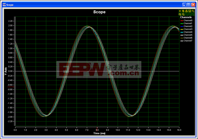
The MAX11040 integrates four 24-bit, sigma-delta ADCs to enable 4-channel simultaneous sampling. Unlike multiplexed-channel sigma-delta ADCs that do not maintain phase integrity, the MAX11040 not only records the phase information but also allows the user to program phase on individual channels. Figure 1 shows same analog signal applied (zero phase delay) to all four ADC inputs, and the resulting sampled data.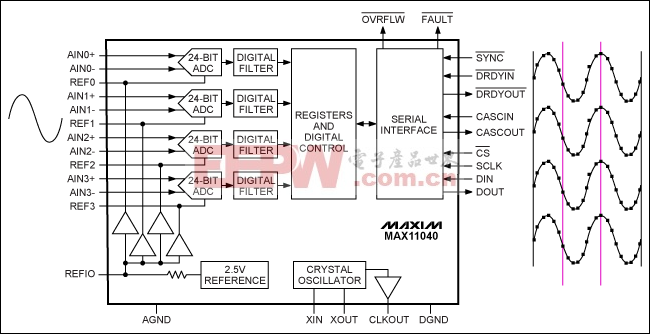 Figure 2 shows the sampled output when zero phase delay is programmed and when varying phase delays are programmed. In both cases, all four inputs are tied to the same signal source.
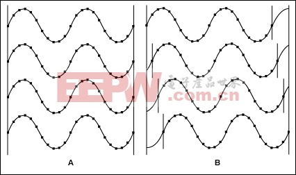 Figure 3 shows the device setup
- The CASCOUT signal from first device is fed into CASCIN of the second device. The setup is similar for second device to the third and following devices. Finally, active-low DRDYOUT from the last device signals that the data is ready from all devices.
- The active-low CLKOUT signal from the first device is fed into active-low XIN of all the other devices.
- Active-low FAULT and active-low OVRFLW are in a wired-OR arrangement.
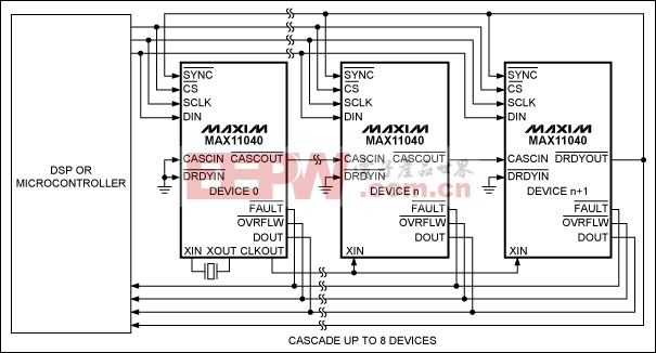 Figure 4 illustrates the process for a fast-moving input; Figure 5 illustrates the process for a slow-moving input. For the fast signals, the transition on the active-low OVERFLOW and FAULT signals is almost simultaneous. One should note that there is a latent period from when the signal crosses the threshold and before the active-low OVERFLOW and FAULT signals go low. There is a similar recovery time before the signals return high.
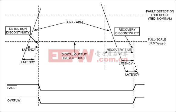 Figure 5. High-frequency analog input OV detection and recovery for a slow-moving input.
Example Data
The following example data was generated with the MAX11040 EV kit.
Simultaneous Sampling, Programmable Phase Delay, and Cascadable Device Setup
Figure 6 shows the block diagram of two ADCs. The settings were programmed for various phase delays. An AC signal of 4VP-P running at 120Hz was provided to the 8 inputs (four inputs for each device). The phase delay for each channel was programmed with the following codes:
| CH1 | 0 | 0 | 0µs |
| CH2 | 36 | 36 | 46.88µs |
| CH3 | 2 × 36 | 72 | 93.75µs |
| CH4 | 3 × 36 | 108 | 140.62µs |
| CH1 | 4 × 36 | 144 | 187.50µs |
| CH2 | 5 × 36 | 180 | 234.38µs |
| CH3 | 6 × 36 | 216 | 281.25µs |
| CH4 | 7 × 36 | 252 | 328.12µs |
 More detailed image (PDF, 269KB)
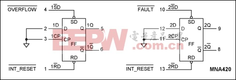 By using voltage and current transformers to bring down the voltage to acceptable levels, two MAX11040s can be cascaded to monitor three phases plus a neutral voltage and current signals. Although a sigma-delta ADC with 24-bit accuracy, the MAX11040 has sufficient sampling rates to monitor greater than 24 harmonics (industry standard). With ENOB of nearly 18, electrical noise as well as large transients can be captured to help determine the quality of power. Phase shifts that can create offsets in your power-factor calculations can easily be compensated by programming phase delays. At the same time overflow and fault can be easily detected and captured.
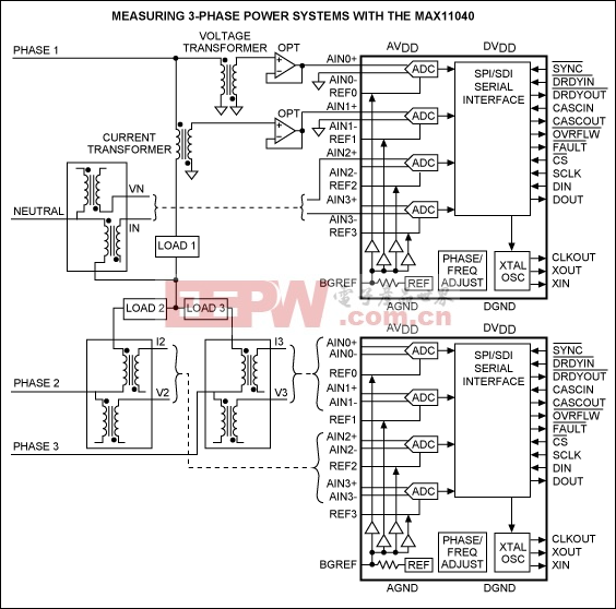
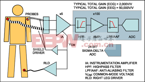 With a high dynamic range, a second gain stage can be eliminated to reduce component count and cost, and improve reliability. Having a sigma-delta architecture with a fifth-order modulator, the MAX11040 provides excellent noise performance compared to SAR and other architectures. It also provides 32 channels with phase adjust to monitor many parts of the brain simultaneously.
评论