How to Increase the Bandwidth

Abstract: A simple circuit technique is described to increase the bandwidth of digital potentiometers by a factor of 10 to 100. Using this technique can enable digital potentiometers to be used in high frequency applications at video bandwidths. Digital potentiometers (or digital pots, or digipots) are extremely useful for controlling or adjusting circuit parameters. Normally they are only used in DC or low frequency applications due to the inherent bandwidth limitations of the digital pots. Typical -3dB bandwidths are from 100kHz to several MHz, depending on the part. However, by using the simple technique described below, you can increase the signal bandwidths of a potentiometer circuit by 10 to 100 times. You can achieve 0.1dB bandwidths of 4MHz and -3dB bandwidths of over 25MHz. Using this technique, digital pots become a viable option for video or other high-speed applications.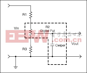 To calculate the transfer function of the circuit (VOUT/VIN), it is useful to use a different model for the potentiometer - see Figure 2. In this figure, R2 has been broken into R2top and R2bottom, where R2top is the portion of the resistance above the wiper, and R2bottom is the portion of the resistance below the wiper. Assuming we are using a pot with a 10kΩ end-to-end resistance (and neglecting the affect of wiper resistance), the ideal transfer function of R2top and R2bottom vs. digital code is as shown in Figure 3. The two end-points and the mid-point of the transfer function are useful to note:
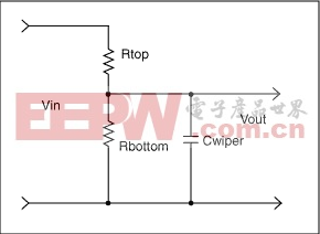

Limited Adjustment Range
The technique takes advantage of the fact that in many digital potentiometer applications, the pot is used to fine tune the signal and does not need the full adjustment range of 0% to 100%. Examples are a one-time factory calibration. In these instances, the digital pots usually provide an overall adjustment range of 10% or less. It is this limited adjustment range which is the key to the bandwidth improvements.Typical Applications Circuit
A typical potentiometer circuit configuration is shown in Figure 1. Here, a digital pot is used to vary the attenuation of a signal. The Digital Pot is R2 and its parasitic capacitance (Cwiper) is also shown. This capacitance is inherent to all digital pots, and is what limits the circuit bandwidth. R1 and R3 are used to limit the signal attenuation caused by the digital pot, as the pot code swings from 0 code to full-scale code.To calculate the transfer function of the circuit (VOUT/VIN), it is useful to use a different model for the potentiometer - see Figure 2. In this figure, R2 has been broken into R2top and R2bottom, where R2top is the portion of the resistance above the wiper, and R2bottom is the portion of the resistance below the wiper. Assuming we are using a pot with a 10kΩ end-to-end resistance (and neglecting the affect of wiper resistance), the ideal transfer function of R2top and R2bottom vs. digital code is as shown in Figure 3. The two end-points and the mid-point of the transfer function are useful to note: - (1) When the Pot code = 0, R2top = 10kΩ and R2bottom = 0kΩFigure 2. The digital Pot with R2 broken into R2top and R2bottom.
 Figure 4. Typical Digital Poteniometer circuit configuration with new model for digital potentiometer.Next, let's make some assumptions:
Assumptions
Assume R2 = 10kΩ (a common digital pot resistance value), and assume we want to attenuate the incoming signal to some arbitrary level, say 70% ±5% of its input value (i.e. from 65% to 75% of its input value).Then using equations (1)–(4), we can see that an adjustment range of 65% to 75%, with a nominal (mid-scale setting) of 70% occurs for:- (5) R1 = 24.9kΩ and R3 = 64.9kΩ.
Bandwidth of Typical Applications Circuit
Using the resistance values of Equation (5), and assuming Cwiper = 10pF, we get the bandwidths as listed in Table 1. Actual wiper capacitance can vary from 3pF to over 80pF, and is function of wiper resistance, the number of steps, the IC process used, and the pot architecture used, among other things. 3pF–10pF of capacitance is fairly representative for 3V to 5V, 10kΩ pots, with 32 to 256 steps. Note that the analysis in this article assumes that it is solely the wiper capacitance in parallel with the pot resistance, which sets the bandwidth. This is valid for relatively straightforward implementations of digital pots, but the bandwidth can be limited even more, if more complicated pot implementations are used. That said, however, the discussions below on improving bandwidth are valid, even though the actual bandwidths one gets might not match exactly what one would initially expect.Table 1. Bandwidth of Circuit of Figure 1, with Resistance Values of Equation 5| Condition | Cwiper = 10pF* | ||
| -0.1dB bandwidth | -0.5dB bandwidth | -3dB Bandwidth | |
| Pot at 0 Code | 106kHz | 245kHz | 702kHz |
| Pot at Mid Scale | 115kHz | 265kHz | 760kHz |
| Pot at Full Scale | 130kHz | 296kHz | 852kHz |
Increasing Circuit Bandwidth
Using Pot with Lower Resistance
One obvious method of increasing the circuit bandwidth is to choose a digital pot with a lower impedance, such as 1kΩ pot, and then scale R1 and R2 accordingly (make them 10 times smaller for a 1kΩ pot than for the circuit with a 10kΩ pot). However, to get digital pots with this low impedance (1kΩ) generally involves a larger die size, which typically translates into higher cost and larger package size, and for this reason, there is a limited availability of pots at 1kΩ.However, if one is available that meets your design needs, the bandwidths quoted above with a 10kΩ pot will increase linearly with the reduction in impedance, i.e. 10 times (assuming the parasitic wiper capacitance doesn't change).For example, using a 1kΩ pot, and setting R1 = 2.49kΩ and R3 = 6.49kΩ, we get a -0.1dB bandwidth of 1.15MHz and a 7.6MHz -3dB bandwidth, with a 10pF wiper capacitance, and with the pot set at mid scale. This is 10 times the bandwidth shown in Table 1, as expected.Using 10kΩ Pot and Changing Circuit Topology
Using a High-Resolution Pot and Restricting the Codes
Compared to 1kΩ pots, there is a much better selection of 5kΩ and 10kΩ pots to choose from - with more pots available in small packages, more with either volatile or non-volatile memory, and more with various digital interfaces to choose from (up/down, I²C, SPI) and more with various amounts of adjustment steps (32, 64, 128, 256, etc.) to choose from. It was for this reason that a pot with 10kΩ end-to-end resistance was chosen for the following design example.Assume due to cost, size, the desired interface, and the required number of pot adjustment steps that it's desirable to use a pot with a 10kΩ end-to-end resistance; how should one go about increasing the bandwidth of the circuit in Figure 1?One method of increasing bandwidth is to eliminate resistors R1 and R3, and simply use a pot with more steps than would be required in the circuit of Figure 1. For example, instead of using a 32 step pot, and getting a 10% adjustment range, as discussed above, you could use a 256 step pot, remove R4 and R6, and simply limit the adjustment range of the pot to those codes that provide the desired attenuation - let's continue with the design target from above - 65% to 75%. This method is illustrated in Figure 5. The codes to use are those from code 0.65 × 256 ( = 166.4, use 166) to code 0.75 × 256 ( = 192). A 256-step pot was used in this example; since the restricted use of codes limits the number of usable steps to 26 (i.e. an adjustment range of about 10% uses about 10% of the available 256 steps). This 26 step usable range corresponds closely to the 32 step range in the examples above.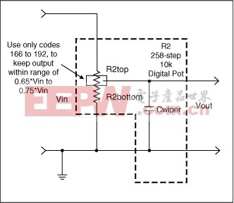 A less-costly solution, that will also provide much better performance, is to add some discrete resistors to the circuit of Figure 1, as shown in Figure 6.
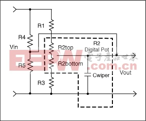 Setting the gain of the potentiometer circuit and limiting its adjustment range by using parallel devices (R4 and R5), instead of by simply only using series devices R1, R2 and R3), is what allows this circuit to achieve better bandwidths than those of Figure 1. It should also be noted that resistors R1, R2, and R3 also affect the gain of the circuit, but since their series resistance is so much larger than R4 and R5, their effect is minimized.The effect of R4 and R5 on the circuit of Figure 6 can be best understood by a few simplifications. In Figure 7, the resistors in the top part of the circuit are combined using the equation in that figure. Note that since R4 is in parallel with R1 and R2top, it lowers the circuit impedance.
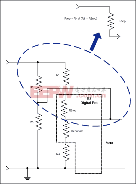

 Using the equations in Figure 9, we can come up with values for R1, R3, R4, and R5, and can then calculate the resultant bandwidths.Using a spreadsheet, one can find component values that satisfy the equations in Figure 9:
 - (6) R1 = 3.48kΩ, R2 = 10kΩ, R3 = 4.53kΩ, R4 = 1kΩ, and R5 = 2.8kΩ.
| Condition | Cwiper = 10pF* | ||
| -0.1dB bandwidth | -0.5dB bandwidth | -3dB Bandwidth | |
| Pot at 0 Code | 4.1MHz | 9.3MHz | 26.3MHz |
| Pot at Mid Scale | 4MHz | 8.9MHz | 25.1MHz |
| Pot at Full Scale | 4.3MHz | 9.6MHz | 27.3MHz |
Summary
This article has shown how by simply adding a few resistors in parallel with a relatively low bandwidth digital potentiometer the resulting bandwidth can be increased by a factor of 100, a significant improvement. This assumes that the applications can tolerate the reduced control range necessary for the improvement. The increased bandwidth can enable the use of digital pots for high frequency applications, previously not considered, such as video signal path control.SPI is a trademark of Motorola, Inc.
DS1267±5V、双路、数字电位器芯片(, 328kB)
DS1669Dallastat数字电位器(, 180kB)
DS1803可编址、双路数字电位器(, 304kB)
DS1805可编址数字电位器(, 260kB)
DS1806六路、数字电位器(, 296kB)
DS1809Dallastat(, 128kB)
DS1844四路数字电位器(, 272kB)
DS1867双路数字电位器,带有EEPROM(, 320kB)
DS1868双路、数字电位器芯片(, 284kB)
DS18693V、Dallastat数字电位器(, 144kB)
MAX5402256抽头、µPoT、低漂移数字电位器(, 224kB)
MAX5403双路、256抽头、低漂移、数字电位器,10引脚µMAX封装(, 444kB)
MAX5413双路、256抽头、低漂移、数字电位器,14引脚TSSOP封装(, 544kB)
MAX5450双路、256抽头、增/减控制接口数字电位器(, 492kB)
MAX5451双路、256抽头、增/减控制接口数字电位器(, 492kB)
评论