Driving Strain-Gauge Bridge Se


Driving Strain-Gauge Bridge Sensors with Signal-Conditioning ICs
Abstract: Strain-gauge sensors - reliable, repeatable, and precise - are used extensively in manufacturing, process control, and the research industries. They transduce (convert) strain into an electrical signal for use in pressure sensors, weight measurements, force and torque measurements, and materials analysis. A strain gauge is simply a resistor, whose value varies with strain in the material to which it is bonded. The article covers the MAX1452 sensor signal conditioner for temperature compensation. The MAX1452's flexible approach to bridge excitation gives the user a substantial amount of design freedom. This article has focused on voltage drive with and without a current boost, but many other bridge-drive configurations can be implemented. Other design considerations include the use of external temperature sensors on the control loop, and achieving sensor linearization (i.e., nonlinearity with respect to the measured parameter) by feeding the OUT signal into this loop. Available strain gauges feature a large range of zero-strain resistance. Sensor materials and technology account for the broad range, but several values (such as 120Ω and 350Ω) have become prominent through widespread usage. In the past, standard values simplified strain measurements by allowing an easy hookup to a basic magneto-deflection meter that included matching input-resistance networks.
Types and Composition of Foil Gauges
Foil-gauge manufacturing employs a limited number of alloys, chosen to minimize the difference between the temperature coefficients of the gauge and the material under strain. Steel, stainless steel, and aluminum constitute the majority of sensor materials. Beryllium copper, cast iron, and titanium are used as well, but the "majority" alloys drive the high volume, low-cost manufacture of temperature-compatible strain gauges. The 350Ω constantan-foil strain gauge is probably the most common.Thick- and thin-film gauges, whose reliability and ease of manufacturing are attractive for automotive applications, are usually produced on a ceramic or metal substrate with an insulating material deposited on the surface. The gauge material is deposited on top of the insulating layer by a vapor deposition process. The sensing gauges and interconnect lines are carved into the metal by laser vaporization or by photo-mask and chemical etch techniques. A protective insulating layer is sometimes added to protect the gauges and interconnects.Gauge materials usually include a proprietary blend of metals chosen to produce the desired gauge resistance, resistance variation with stress, and (for temperature stability) the best temperature-coefficient match between sensor and base metal. Nominal gauge and bridge resistances of 3kΩ to 30kΩ have been developed for this technology, which has been used to manufacture both pressure and force sensors.
Bridge Excitation Techniques
A Wheatstone bridge is usually employed in strain-gauge sensors based on foil, thin film, or thick film. The Wheatstone bridge converts the gauge's strain-induced resistance changes into a differential voltage (Figure 1). With excitation voltage applied to the +Exc and -Exc terminals, a strain-proportional differential voltage appears at the +VOUT and -VOUT terminals.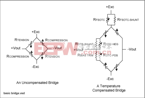
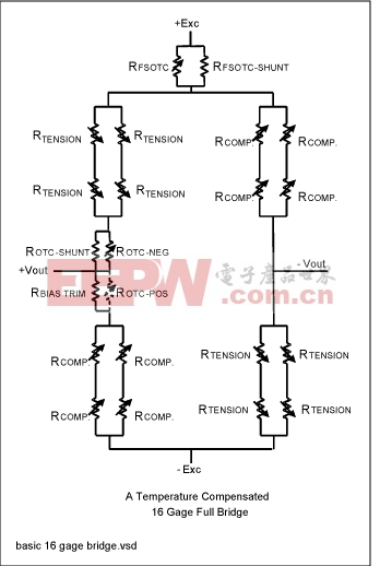 As temperature changes, resistors RFSOTC and RFSOTC_SHUNT modulate the bridge excitation voltage. Typically, the RFSOTC material has a positive temperature coefficient that reduces the bridge excitation voltage as temperature increases. Sensor outputs become increasingly sensitive to load as the temperature increases. Decreasing the bridge excitation voltage effectively cancels inherent temperature effects by reducing the sensor output. Resistor RSHUNT is not sensitive to temperature or strain, and is used to trim the amount of TC compensation delivered by RFSOTC. An RSHUNT value of 0Ω would cancel all effects of RFSOTC, while a value of infinity (open circuit) would enable the full effect of RFSOTC. This technique compensates first-order temperature-sensitivity effects quite well, but does not address the more complicated and higher-order nonlinear effects.Temperature compensation of offset change is accomplished by inserting a temperature-sensitive resistor into one arm of the bridge. These resistors are shown in Figures 1-3 as ROTC_POS or ROTC_NEG. Again, a shunt resistor (ROTC_SHUNT) trims the amount of temperature influence introduced by ROTC_POS or ROTC_NEG. Whether to use ROTC_POS or ROTC_NEG depends on whether the offset has a positive or negative temperature coefficient.
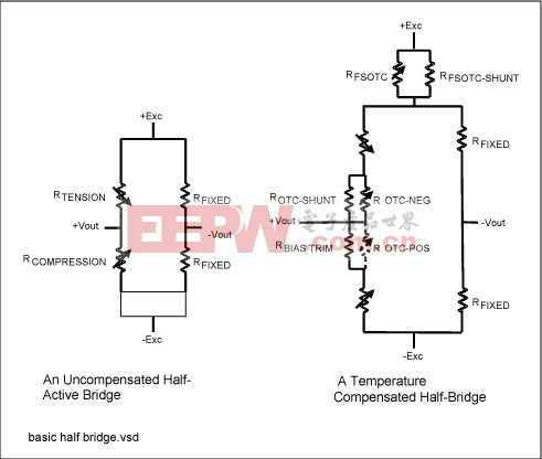
How to Enable Current Excitation Drive
Using current to excite the bridge sensor causes difficulty because the bridge resistance changes with load, and because current overrides or negates the built-in sensitivity-compensation networks (shown as RFSOTC and RFSOTC-SHUNT in Figure 2).Various means are available to circumvent these problems and enable a current excitation drive. An easy approach is to use the MAX1452 in a configuration that delivers a voltage drive. That circuit includes the minimal number of external components needed to provide the high levels of current necessary with voltage excitation. The MAX1452 is a complete and highly integrated signal-conditioning IC that performs sensor excitation, signal filtering and amplification, and temperature linearization of both offset and sensitivity.The MAX1452 was designed primarily for the silicon Piezo-Resistive Transducers (PRTs) often used in sensing pressure. It incorporates four 16-bit delta-sigma DACs (D-A converters), a temperature sensor, and temperature-indexed coefficient tables for performing temperature compensation and linearization of bridge sensors (Figure 4). Temperature compensation and amplification are accomplished with an analog signal path between the sensing element and the voltage output. This IC readily accommodates foil or thick film strain gauges with the addition of minimal external circuitry to provide a voltage-based excitation and extra current-drive capability for the Wheatstone bridge.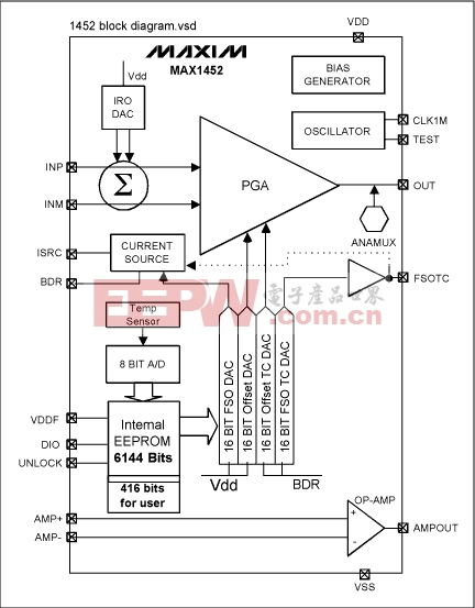
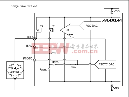 Resistor RSTC enables first-order modulation of the sensor-excitation current as a function of temperature. For silicon PRT transducers, temperature is derived from the resulting sensor bridge voltage when a current is passed through the bridge. Such sensors feature a very good transfer function between the bridge resistance and temperature. By exciting the bridge with current, you can scale the resulting bridge voltage and use it for first-order compensation of offset and sensitivity. This is accomplished by routing the bridge voltage (pin BDR) to the reference input of the full-scale output temperature-compensation DAC (FSOTC DAC). Remember, however, that current excitation does not generally apply when foil or thick-film strain gauges are used.
Voltage-Drive Circuits
The MAX1452's internal 75kΩ resistors can serve for RISRC and RSTC, or external resistors can be routed by switches SW1 and SW2, as shown in Figure 5. The ISRC pin gives access to the op amp and allows voltage feedback from the bridge drive. Figures 6, 7, and 8 depict three different voltage-drive circuits.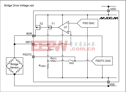 Figure 7. Circuit diagram featuring npn transistor for low-resistance sensors.
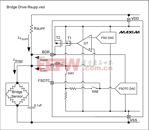 Low resistance (120Ω to 2kΩ) strain gauges or thick-film resistors wired in a Wheatstone bridge circuit cannot be driven from T2 directly. Use of an external npn transistor in an emitter-follower configuration (Figure 7) solves this problem. Current through the npn transistor is drawn directly from the VDD power rail at the collector. Op amp U1 raises the bridge voltage by driving T1 and T2 sufficiently into conduction to turn on the npn transistor. To close the loop, the bridge voltage at ISRC is fed back to the op amp. Bridge voltage is regulated to match the FSO DAC output voltage, and a small 0.1µF capacitor is added across the bridge for stability.The npn transistor's base-emitter voltage (VBE) has a significant temperature coefficient, but that effect is regulated out of the equation by feedback to U1. At cold temperature, where VBE is large, the maximum bridge voltage is limited:VBRIDGEMAX = VDD - VT2SAT - VBELike the VBE tempco, the gain of TNPN has a temperature component that is regulated out of the equation by the control feedback loop.Another method of supplying sufficient drive current to a low-resistance bridge is to add a small external resistor in parallel with T2 (RSUPP in Figure 8). The RSUPP value ensures that the bridge voltage is slightly less than the desired value (3.0V for VDD = 5.0V). T2 then supplies additional current that raises the bridge voltage to the desired value. Because T2 in the OFF state is the lowest current T2 can supply, RSUPP should be sized for the worst-case low bridge voltage. Also, T2's maximum current capability (2mA at VBDR = 4.0V) determines the maximum bridge-voltage modulation allowable. This circuit is useful for bridge sensors with a relatively low temperature coefficient of sensitivity (TCS) which does not require significant bridge-voltage modulation.Sensitivity effects introduced by the temperature coefficient of RSUPP are regulated out by the feedback to U1. To assure an adequate drive-current margin when designing the circuit, be sure to consider the power-derated maximum and minimum for RSUPP.
Summary
The MAX1452's flexible approach to bridge excitation gives the user a substantial amount of design freedom. This article has focused on voltage drive with and without a current boost, but many other bridge-drive configurations can be implemented. Other design considerations include the use of external temperature sensors on the control loop, and achieving sensor linearization (i.e., nonlinearity with respect to the measured parameter) by feeding the OUT signal into this loop.
MAX1455 pdf datasheet
评论