Understanding the Effects of C


Understanding the Effects of Clock Tolerances on 50/60Hz Noise Rejection in High Performance Sigma Delta ADCs
Abstract: This article explores the effect of clock tolerance on the performance of the lowpass decimation and digital filter inherent in sigma-delta ADCs, and especially the filter notch frequencies. Low-bandwidth sigma-delta applications commonly take advantage of the digital filter to provide 50Hz, 60Hz, or simultaneous 50Hz/60Hz noise rejection. It is important to understand the relationship between clock frequency and filter characteristics of the digital filter when choosing an external clock crystal or selecting an internal clock. Sigma-delta ADCs use a modulator to convert an analog input to a series of impulses. The ratio of 1's to 0's on the modulator output represents the average value of the analog input. The output of the modulator goes to a digital filter. Common implementations of the digital filter in sigma-delta ADCs are a lowpass filter with a SINC (Sin(x)/x) impulse response. The filter's output goes to a decimator to reduce the data rate of the output data.Besides the obvious function of filtering the quantization noise, the SINC filter has the added benefit of providing filter notches at integer multiples of the data output rate. For example, a 60Hz data output rate will have notches at 60Hz, 120Hz, 180Hz, etc. By strategically tuning filter notches at frequencies of known noise sources, (i.e., 50Hz or 60Hz powerline noise), substantial noise rejection can be realized. This is useful when using high-resolution sigma-delta ADCs to measure low bandwidth, low-level signals in the presence of 50Hz/60Hz noise.The output data rate and frequency of the filter notches are functions of the modulator frequency, decimation ratio, and filter order. The decimation ratio is the ratio of the modulator frequency and the output data rate. The modulator frequency is a function of the ADC clock frequency.The SINC filter, which is typically 3rd order and denoted SINC³, is defined in the frequency domain as:
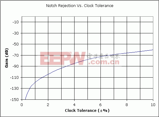
H(f) = [1/N * Sin(N*π*f/fM) / Sin(π*f/fM)]³Where: N is the decimation ratioFigures 1, 2, and 3 shows a SINC³ filter response with a 60Hz notch frequency, 19.2kHz modulator frequency, and a decimation ratio of 320. Use the Maxim Online Sigma-Delta 50Hz/60Hz Rejection Calculator to evaluate notch frequency rejection for different device operating modes.Figure 1 shows the filter response with a nominal clock frequency. This filter response achieves a near infinite 60Hz rejection at the filter notch. Figure 2 shows the same SINC³ filter response but with a ±4% clock tolerance. This filter shows a -83.7dB rejection at the notch frequency.Figure 2. ±4% clock tolerance gives 83.7dB of 60Hz rejection (worst case). While external clocks can be accurately controlled, internal oscillators are factory trimmed to within a specified accuracy. Figure 3 shows the worst-case rejection at the notch frequency for a clock accuracy with the same parameters as Figures 1 and 2.
Improved processes have allowed manufacturers to integrate reasonably accurate clocks into sigma-delta ADCs. High-resolution sigma-delta ADCs like the MAX1415/MAX1416 feature internal oscillators, thereby reducing the need for external crystals or external clock sources and saving board space. A typical operating mode shows a minimum of 83.7dB 60Hz rejection with the ±4% internal clock specification. This is sufficient for many applications.
评论