Abstract: This application note discusses the delivery of Carrier Ethernet services and illustrates the need for demarcation. The requirements of Carrier Ethernet demarcation are outlined, and the anatomy of a demarcation point is provided with a framework of the major functional blocks. Technologies related to each block of the demarcation point are discussed in the context of optical network topology, and strategies for choosing technologies are outlined and compared. A similar version of this article was featured in Maxim's Engineering Journal, vol. 63 (PDF, 1.3MB).The Metro Ethernet Forum (MEF) has now standardized a number of services for wide-area Ethernet connectivity, collectively known as Carrier Ethernet Services. The MEF's goal in defining these services is to encourage the ubiquitous adoption of Ethernet by promoting the interoperability of high-quality Ethernet services among service providers. To ensure that consumers of these services can compare features across service providers, the MEF has also defined measurable attributes for each service. These attributes must be meaningful to consumers. Therefore, they must be representative of the observable service characteristics at the point where a customer physically connects their network to the service provider's network. The physical interface where this connection occurs is known as the demarcation point.Service demarcation has been common practice for telephone service providers ("Carriers") for decades. The most familiar form of demarcation is the small box mounted outside almost every suburban residence, connecting the local Carrier's phone network to the wiring of the house and providing wireline phone services to the resident. This small box is a type of demarcation unit. The demarcation unit is where the customer's responsibilities end, and the Carrier's responsibilities begin.For telephone services, the functional requirements of the demarcation unit are minimal. With Carrier Ethernet services, however, the requirements of the demarcation unit are much greater. The Carrier normally provides the customer with a contractual service-level agreement (SLA), which defines attributes of the service such as committed information rate (CIR), committed burst size (CBS), service availability, frame delay, frame jitter, frame-loss rate, and fault-recovery time. A Carrier Ethernet demarcation unit plays a critical role in ensuring that the actual service attributes adhere to the commitments of the SLA.Requirements of DemarcationAt the very minimum, an Ethernet demarcation unit provides a physical connection and measurement point: either an RJ-45 jack or an optical connector. The physical-layer interconnect has been defined by the IEEE® and is included in the MEF specifications by reference. The demarcation unit must accept standard IEEE 802.3 Ethernet frames from the subscriber and prepare them for transport across the service provider's network. The functionality beyond these minimal requirements varies by application.The customer-interfacing part of the demarcation function is called the user network interface (UNI). The MEF is standardizing a range of functionality for the UNI, from the most basic UNI Type 1 up to the autoconfiguring UNI Type 3. The MEF recently approved a specification called MEF 13 UNI Type 1 Implementation Agreement and the associated certification-testing process. UNI Type 2 and Type 3 are outlined in MEF 11 and are expected to be expanded upon by the MEF in the future.MEF 13's UNI Type 1.2 requires that demarcation units be able to process certain layer-2 protocols arriving at the UNI from the customer's network. This requirement forces the demarcation unit to have layer-2 visibility and filtering. Furthermore, the ITU and MEF requirements for UNI Type 2 and Type 3 to perform certain layer-2 management protocols force the demarcation unit to have full layer-2 processing capability—at least, at a low level of throughput. These requirements impact technology decisions when architecting a demarcation unit design. One beneficial side effect of these requirements is that most demarcation unit designs have some processing power available for adding valuable higher-layer application functionality.Anatomy of a Demarcation UnitFigure 1 shows the basic functional blocks of an Ethernet demarcation unit. The functional blocks that interface with the customer's network are shown on the right side of the diagram under "UNI," while the functional blocks that interface with the Carrier's transport network are on the left under "network interface." The group of network interface functions are called the network interface device (NID). Although the term NID has also been used to refer to a stand-alone piece of equipment, it is used here to describe a functional part of demarcation. The MEF currently has a standard for NID functionality in draft form, but has not yet approved it. The NID function may, or may not, be in the same piece of equipment as the UNI. In practice, the dividing line between the UNI and NID varies. To further confuse the issue, the MEF has defined a range of UNI subtypes. Specifically, a demarcation unit normally contains the UNI-network (UNI-N) interface or external network-to-network interface (E-NNI).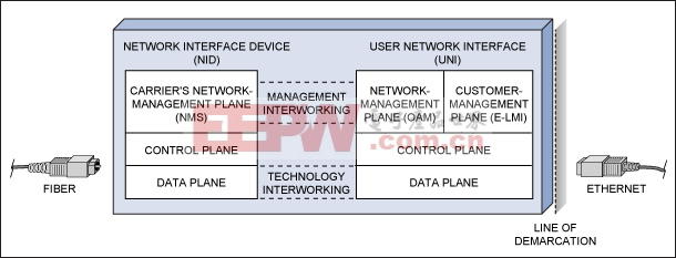 The UNI and NID typically have separate control-plane software that handles low-level configuration and status monitoring. Examples of activities handled by the control plane are: detection of a cable connection or disconnection, status and performance monitoring, and the handling of interrupt events. The control plane is responsible for ensuring that the service is provided as instructed by the management plane. The control plane is normally implemented in software running on a local microprocessor that configures and controls the data-plane hardware. In stand-alone demarcation units, it is common for the control planes of the UNI and the NID to run on the same processor. The control and data planes can sometimes be implemented in one NPU, although doing so can lead to complex data- and control-plane corruption issues. Architectures that maintain a clear separation between the data and control planes are usually easier to implement.Management planes are normally implemented in software at the line-card or chassis level. The UNI and NID both have management planes for fault recovery, SLA performance monitoring, etc. The management plane's primary purpose is to handle issues that concern the network operator. The MEF has defined the structure for the network operator's management information in MEF 7 EMS-NMS Information Model. Optionally, the UNI may also have a customer-facing management plane in addition to its network-facing management plane. The MEF has defined a basic structure for this customer-facing management interface in MEF 16 Ethernet Local Management Interface (E-LMI). The management planes for the UNI and NID can exchange information, but it is not a requirement.The UNI management plane also uses a special protocol for Ethernet management defined by ITU-T and IEEE, called Ethernet OAM (operation, administration, and maintenance). IEEE 802.3ah OAM monitors the operation and health of a single point-to-point link and improves fault isolation. ITU-T Y.1731 OAM increases the scope to include advanced multiple-link operations, such as link tracing, connectivity checking, and automatic protection switching. Using OAM, the network operator can perform management tasks that were unavailable on Ethernet networks only a few years ago. The UNI and NID typically have separate control-plane software that handles low-level configuration and status monitoring. Examples of activities handled by the control plane are: detection of a cable connection or disconnection, status and performance monitoring, and the handling of interrupt events. The control plane is responsible for ensuring that the service is provided as instructed by the management plane. The control plane is normally implemented in software running on a local microprocessor that configures and controls the data-plane hardware. In stand-alone demarcation units, it is common for the control planes of the UNI and the NID to run on the same processor. The control and data planes can sometimes be implemented in one NPU, although doing so can lead to complex data- and control-plane corruption issues. Architectures that maintain a clear separation between the data and control planes are usually easier to implement.Management planes are normally implemented in software at the line-card or chassis level. The UNI and NID both have management planes for fault recovery, SLA performance monitoring, etc. The management plane's primary purpose is to handle issues that concern the network operator. The MEF has defined the structure for the network operator's management information in MEF 7 EMS-NMS Information Model. Optionally, the UNI may also have a customer-facing management plane in addition to its network-facing management plane. The MEF has defined a basic structure for this customer-facing management interface in MEF 16 Ethernet Local Management Interface (E-LMI). The management planes for the UNI and NID can exchange information, but it is not a requirement.The UNI management plane also uses a special protocol for Ethernet management defined by ITU-T and IEEE, called Ethernet OAM (operation, administration, and maintenance). IEEE 802.3ah OAM monitors the operation and health of a single point-to-point link and improves fault isolation. ITU-T Y.1731 OAM increases the scope to include advanced multiple-link operations, such as link tracing, connectivity checking, and automatic protection switching. Using OAM, the network operator can perform management tasks that were unavailable on Ethernet networks only a few years ago.UNI TechnologiesThe network transport technology options for the UNI are limited by the scope of the MEF standards to full-duplex 10Mbps, 100Mbps, 1Gbps, or 10Gbps IEEE-compliant electrical or optical Ethernet. To effectively cover a range of physical connections, some demarcation units simply allow a small form-factor pluggable (SFP) module to be inserted and, thus, configure the UNI's physical interface at the time of installation. The rest of the required UNI data-plane functionality is then implemented independent of the physical interface by using an Ethernet mapper, NPU, or FPGA. The alternative to the SFP approach is to use an on-board PHY or optical module. This alternative sacrifices some flexibility for a lower total solution cost.NID Technology Driven by Location in the NetworkFigure 2 illustrates two common demarcation situations. At site A, direct optical-network access is available at, or very near to, the customer's premise. This situation is common in metropolitan networks and in intercarrier handoffs known as E-NNI. When the demarcation point is on the optical edge, the NID must connect either directly to the optical network or to a lower-rate tributary made accessible by a piece of optical-networking equipment. The choice of NID technologies for applications on the optical edge runs a wide range: traditional SONET/SDH, Ethernet-over-PDH-over-SONET/SDH (EoPoS), provider backbone bridge (PBB), transport multiprotocol label switching (T-MPLS), passive optical networking (PON), dense-wave division multiplexing (DWDM), resilient packet ring (RPR), optical Ethernet, and hybrid fiber-coax (HFC).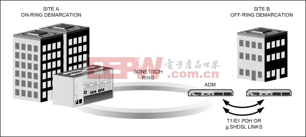 The use of a particular transport technology for a given NID is dictated by what will be the most cost-effective interface with the Carrier's existing network at the point where the service needs to be delivered. It is beneficial when architecting a demarcation platform to use a modular design to cover a range of expected UNI and NID transport technologies. The use of a particular transport technology for a given NID is dictated by what will be the most cost-effective interface with the Carrier's existing network at the point where the service needs to be delivered. It is beneficial when architecting a demarcation platform to use a modular design to cover a range of expected UNI and NID transport technologies.The State of the Art in Ethernet MappingTypically, an integrated Ethernet mapping device performs the UNI-NID interworking function in an Ethernet demarcation unit. EoS and EoPDH mappers are the two most common mapping technologies. EoS mappers have been prevalent for almost ten years, but EoPDH mappers have been available for less than two years. The recently announced DS33X162 family of EoPDH Ethernet mapping products from Maxim optimally meets the needs of today's demarcation designs. The product family includes nine devices ranging from one to sixteen PDH links, and is the industry's only solution that covers the complete range of ITU-standardized EoPDH mapping possibilities with a single software/hardware footprint. All devices in the product family maintain critical control- and data-plane separation, while still allowing flexibility for valuable higher-layer protocol implementations.Going Beyond the Minimum RequirementsThe MEF has only standardized a minimum set of UNI functions at this time. Yet, there is plenty of room for equipment makers to integrate value-adding functions to differentiate their demarcation unit from the competition while maintaining compliance. The value-adding features fall into two categories: features that help sell the demarcation unit to the Carrier, and features that help the Carrier sell the service to their customers.Cost of installation is a primary concern to Carriers. A demarcation unit with features for automatic provisioning and built-in, network diagnostic testing lowers total installation cost. The use of technologies that can deliver midband Ethernet while reusing existing equipment and infrastructure, such as EoPDH, also reduces costs for the Carrier. Real-time SLA monitoring and seamless integration into the Carrier's existing network-management system (NMS) also add significant value to Carrier services.Service customers, meanwhile, value convenience and reliability. An example of a convenience feature is a web-browser-based (HTML) management interface that provides a complete overview of the health of all the customer's UNIs with a single glance. The interface could be served from the UNI itself, or it could reside in a central location and collect information from all of the customer's UNIs. The same HTML subscriber interface can provide SLA-compliance reporting for each UNI over time, bandwidth-usage profile reporting, and configuration options for quality of service.Customers also might want to utilize VLAN tagging to provide varying qualities of service to different VLANs or applications. Enterprise network administrators need automatic status monitoring using their existing network-management tools, such as SNMP, or they need to receive notifications through email alerts. Growing businesses want to be able to incrementally expand their bandwidth as their consumption increases. NID technologies that utilize VCAT/LCAS link aggregation make it easy to add bandwidth. The demarcation unit can provide for dynamic provisioning to increase the available bandwidth during periods of high demand, and decrease the bandwidth in times of low demand. These are just a few examples, but they give an idea of what is possible in the future.Now that the MEF has defined a common starting point with MEF 13, demarcation unit architects have a common foundation on which to build tomorrow's demarcation technology.A similar version of this article was published in the May 2008 issue of Lightwave. IEEE is a registered service mark of the Institute of Electrical and Electronics Engineers. |


评论