Dual Comparator Forms Temperat


Dual Comparator Forms Temperature-Compensated Proximity Detector
Abstract: Simple comparator and op amp circuit forms a temperature-compensated proximity detector. In the proximity detector shown in Figure 1, a 4-inch-square piece of copper-plated PC board serves as an antenna that forms one plate of a capacitor. An approaching (grounded) person serves as the other plate, producing a capacitance value (in the 2pF to 5pF range) that increases as the person approaches. At 6 inches from the copper plate, for example, the person produces a capacitance value of about 2pF.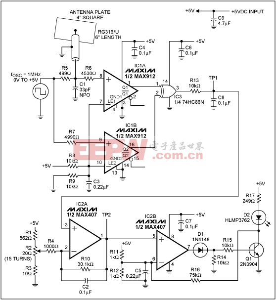
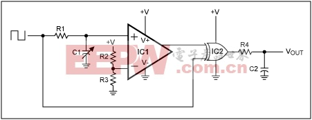 Figure 1's delay capacitance consists of a 33pF capacitor (C1) in parallel with 15pF (6 inches of coaxial cable at 30pF per foot) and the 4-inch-square antenna plate. It charges to 5V via R5 during each positive half cycle of the input square wave. When no body is near the detector, this capacitance equals 48pF and produces a delay of 16.5ns at the upper XOR input. With a hand placed 6 inches from the detector, the capacitance rises to 50pF and produces a delay of 17.3ns, yielding a time difference of only 0.8ns.To detect such small time differences—over temperature and with accuracy—the comparators must be very stable in offset voltage and propagation delay (delay time is affected by changes in offset voltage as well as propagation delay). A single 10ns comparator is generally stable to within 1ns, but resolving subnanosecond intervals requires the dual-comparator approach of Figure 1, which increases the useful resolution by a factor of four to five.Op amp IC2A offsets and amplifies the DC voltage at TP1, which corresponds to the distance between a hand and the antenna plate. A hand movement toward the antenna causes the voltages at TP1 and TP2 to rise. Op amp IC2B and the transistor serve as a comparator with hysteresis, which compares the TP2 voltage with 2.5V. Thus, any TP2 voltage above 2.5V (which corresponds to a proximity of 6 inches) turns on the LED. The potentiometer (R2) can be adjusted to set a threshold other than 6 inches, and a DVM at TP2 can be connected to read out the proximity in inches (for example). R16 adds hysteresis to ensure a well-defined transition.To compare the compensated and uncompensated circuits for temperature stability, adjust the Figure 1 potentiometer to 2.5V, then measure TP2 of Figure 1 (compensated) and TP1 of Figure 2 (uncompensated) at various temperatures (Figure 3). To ensure frequency stability for the high-speed dual comparator in Figure 1, the copper-clad PC board should have a ground layer in addition to the circuit layer. Power-supply bypassing should include 0.1µF ceramic capacitors placed very close to the comparators' supply terminals.
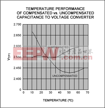
A similar idea appeared in the 2/16/98 issue of EDN.
MAX912/MAX913 pdf datasheet (TTL比较器)
评论