简单的LED电源项目电路ApowersourceforsimpleLEDprojects


简单的LED电源项目电路 A power source for simple LED projects
LED's are great display tools. Their prices have decreased to a point where they are replacing more conventional light sources. In border=0>
The 10 LED's were lit using the following circuit...
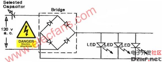
figure 2
The capacitor value may be computed via the following empirical formula. This formula is valid for the circuit shown in Fig.2:
 (1)
(1)
Where "C" is in uFd and "I" is in miliamperes. A design current of 10 mA per LED was selected. Thus for ten LED's, 100mA is the total current. Inserting this current value into the formula, yields a capacitor value of 3.1uFd.
To achieve this value, two capacitors connected in parallel were used. Recall that the total capacitance of capacitors connected in parallel is simply the arithmetic sum of the individual capacitors:

Thus:


figure 3
If it becomes necessary to use capacitors connected in series to achieve a desired total capacitance, the formula for this computation is:

For two capacitors in series, it may be easier to calculate the total series capacitance via:

To achieve a desired total capacitance, it may be necessary to use a series-parallel connection of three capacitors. Empirical formula (1) was derived by measuring currents and voltages for various quantities of LED's (up to 30) connected into the circuit shown in Fig 2. The capacitors must be low loss, non-polarized units with voltage ratings equal to or greater than 200 volts.
Transformer voltage dropping circuit
If instead of using capacitors, it is desired to power LED's with a transformer, the low voltage, rectified sine wave ideally should be applied to each LED via a dropping resistor. This enables the forward current to be adjusted to a value that does not overdrive the LED. In lieu of using dropping resistors, if the rectified voltage is carefully selected via a judicious choice of transformer, the output of a rectifier may be applied directly to align=left>
figure 4
The Tamura transformer has a 4 volts c.t secondary. This value just supplies sufficient voltage to generate 14mA for align=left>Comparing the two approaches, the capacitor voltage dropping circuit is smaller, lighter in weight and varying the capacitor value enables the user to obtain a desired current value for each LED. The transformer approach, yields a circuit where the transformer provides isolation between the LED's and the line voltage. Both circuits are nominally low in parts cost.
Parts
The components used in gathering data where purchased from Mouser Electronics:
- 2.2 uFd = PHE840MZ7220MF14R (2.52)
- 1.0 uFd = PHE840MY7100MD16R (0.93) (275 Volts)
- Tamura transformer #SB2812-1204 (3.53)
- 1N4004 diodes (0.08 each)
The bridge rectifier and LED's were purchased from All Electronics:
- LED-1 (T1-3/4 Red LED) (0.10 each)
- FWB-15, 1-1/2 amp, 400 PIV Bridge Rectifier (0.50 each)
- Perf Board
Acknowledgments: My thanks to Mr. Oscar Ramsey for his testing, data gathering and construction efforts.
评论