
LinearFM50WattwithBLY9050WFM调频功放电路

Linear FM 50Watt with BLY90 50W FM调频功放电路
A amplifier of force RF for the FM, is always essential for the amateur that wants it strengthens some small transmitter, that likely already it has manufactured or has been supplied ready. The present circuit can give 50-60W RF force of expense, with control smaller than 15-20W in the region of frequencies of FM, that is to say in the 88-108MHZ. Transistor that we selected for this manufacture is the BLY90, that has gain 5dB.
Description
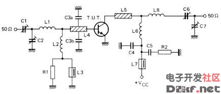
image 1
As it appears in the analytic drawing (image 1) the amplifier is manufactured with transistor TR1, type BLY90 of Philips. The transistor this is specifically drawn for operation in frequencies up to 175MHZ, with very good results of linearity and record of force. In his technical' characteristics they are included the tendency of operation in the 12V the current of collector in the gain expense in the 5dB (measured in order C) and force of entry in the 16W. Variable capacitors C1, C2, with inductor L1, constitute the circuit of co-ordination, that adapts the exit of our transmitter in amplifier RF. This circuit has been calculated suitably, so that it covers all band the FM with the biggest possible output. Inductor RFC1 polarized the transistor, so as to it works in order C, that is to say with the biggest output. Inductor L2 in the collector of TR1, constitutes the charge of amplifier, while RFC2 prevents the RF signals leak in the line of catering. Capacitor C2 and resistance R1, protect the circuit from auto polarization. The coordinated circuit of expense that is constituted by inductor L2 and variable capacitors C3, C4, adapts the exit of amplifier RF with the next stage, which can be constituted from some amplifier RF of high force ( 300W) or a aerial. This circuit can be supplied with 12V f.e from the battery of border=0>
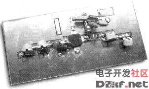
image 2If all they are it includes, you connect the exit of your transmitter (15-20W) in input the amplifier. The exit of amplifier him you will connect in some charge (dummy load) or in the aerial, through bridge stagnant waves. Supply with tendency 11-15V your amplifier (power supply it should gives current 4-5A). Regulate the 4 variable C1-C4, until you take the biggest force of expense. The amplifier is ready.Parts C1-C4 = 10-80pFL1 = 1 coils of diameter of 10mms, 1mmC5 = 10nFL2 = 7 coils of diameter of 10mms, 0,8mmsC6 = 1000pFL3 = 3 coils of diameter of 10mms, 1mmC7 = 100nFTR1 = BLY90C8 = 2200mF/35V

评论