
MAXQ微控制器的中断编程

Abstract: This applicaTIon note describes the interrupt architecture and covers interrupt programming techniques for the MAXQ family of microcontrollers.
IntroducTIon
No special knowledge is implied or required to read this note, but basic familiarity with the MAXQ architecture and register map is a plus. That informaTIon can be found in The MAXQ Family User's Guide, data sheets (e.g., MAXQ2000), and other applicaTIon notes (e.g., Introduction to the MAXQ Architecture; An Example Application Using the MAXQ2000 Evaluation Kit). The source code and project files of the examples used in this application note can be downloaded.
MAXQ10 and MAXQ20 microcontrollers are equipped with a simple, inexpensive single-vector interrupt mechanism, while interrupt sources and controls are organized logically into a three-level hierarchical structure. The hardware does not prioritize interrupts. The application code is responsible for dispatching of various interrupts through the single vector, therefore, programming and debugging the interrupts is an important part of the application development cycle. This note provides:
A starter guide for those who need to program simple interrupt functionality
Hints for implementing more elaborate interrupt priority schemes, nested interrupts, and best utilization of available hardware resources.
MAXQ Interrupt Mechanism Overview
The MAXQ family of microcontrollers has a register IV (Interrupt Vector) which holds the address of the interrupt routine, and a bit INS (Interrupt iN Service) to indicate an interrupt activity. When an interrupt is triggered, the processor core behaves as if "call IV" and "move INS,#1" instructions were inserted in the code. The MAXQ core executes a subroutine call, i.e., the instruction pointer IP is pushed into stack and loaded with the content of the IV register, then it sets the INS bit to signify that there is an active "interrupt in service" preventing further interrupt calls. Interrupt service finishes with the "RETI" (or "POPI") instruction, which pops the return address from the stack into IP and clears the INS bit, and user code resumes from the place where it was interrupted.
The interrupt trigger logic is presented in Figure 1, using the MAXQ2000 microcontroller as an example. Other MAXQ microcontrollers might have different sets of interrupt sources, but the logical structure is generic throughout the entire MAXQ family.
Logical structure begins with the individual interrupt sources listed on the left in Figure 1. Every source has an associated interrupt flag—a special bit that is set by hardware when the interrupt event from that source is detected. Each source also has an individual enable bit, which allows applications to enable or disable the interrupt source. The interrupt signal from that source is only active when both the flag and enable bits are set to 1. These bits provide individual interrupt signaling and control in the MAXQ architecture.
Figure 1. Interrupt trigger logic in the MAXQ2000 microcontroller.
Because the MAXQ architecture is modular, interrupts are also grouped according to their location in modules. Like individual interrupt sources, every module has its own interrupt flag and enable bit, as shown in the middle in Figure 1. The flag is a logical "OR" of all the underlying interrupt signals from that module, while the enable bit allows applications to enable or disable interrupts for an entire module. These bits are allocated in two 8-bit registers (flags in IIR and enables in IMR) and provide interrupt signaling and control at the module level.
Finally, interrupt signals from all modules are "ORed" to form a global interrupt trigger signal, as shown on the right in Figure 1. The "interrupt global enable" bit, IGE, allows applications to disable or enable this signal, providing interrupt control at the global level.
Once set, an individual interrupt flag stays set until cleared by software (i.e., by interrupt service code), even if the condition which caused the flag to set is gone or removed. If software fails to clear the flag, the interrupt will be triggered repeatedly after exiting the service code. A modular interrupt flag (IIR register) is read-only; it is cleared automatically as soon as all underlying individual flags within a module are cleared by application code.
In the configuration shown in Figure 1, the global interrupt trigger signal on the right is active, caused by three individual sources on the left: UART1 Transmit, Timer1 Overflow, and Watchdog Timer. All three have both their individual flag and enable bits set. One more source (Ext8 in module 1 is also signaling, but that signal is masked (disabled) at the module level, because the interrupt mask bit IMR.1 is 0. The software in the interrupt service routine (ISR) identifies the signaling sources by analyzing flags and enable bits (shown in Figure 1 in reverse order, that is, from right to left), then services each active source and clears the individual interrupt flags.
Programming a Simple Interrupt Service Routine
Many applications do not require complex interrupt functionality—just one or two interrupts with no regard to priority. Let's see how to program such service routines for the MAXQ. We use the IAR Embedded Workbench® as an example programming tool, but our code is mostly portable (except for a few tool-specific features, indicated below).
Assume that an existing application needs to fire short pulses on a port pin every millisecond while doing many other important tasks. This could be implemented using an on-board timer configured to produce an interrupt request every 1ms.
To accomplish the interrupt programming we need to add some interrupt-related code to the existing interrupt-less application. The interrupt-related code consists of two parts: the initialization and the ISR. The initialization code is placed somewhere at the beginning of the application to set the proper interrupt configuration: the enable bits (individual, module, and global) and the IV register. The ISR can be placed anywhere, and should perform three basic tasks before exiting:
Identify the source of an interrupt (not necessary if only one source is used)
Clear the interrupt flag
Execute required actions
First, let's see how all this works in assembly language. C-programmers may skip this section, though it does provide helpful insight into what is going on behind the curtains. Figure 2 shows the source code of our interrupt-less application. Besides many other very important tasks, it continuously outputs the byte 0x35 (ASCII symbol "5") at baud rate of 115200. When run on the hardware, the output can be easily captured via the COM port, as shown in Figure 3.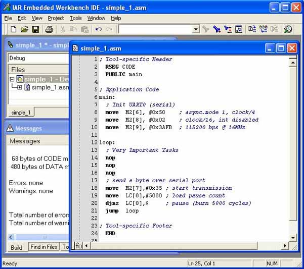
Figure 2. Example application code without interrupts.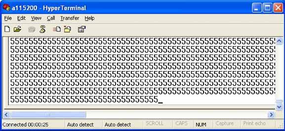
Figure 3. Output of the example interrupt-less application from Figure 2.
Now we add the interrupt code, starting with the ISR, following the four steps outlined above.
Because only one interrupt is active, no source identification is needed;
If we use Timer1 overflow interrupt, the flag is bit 3 of register 8 of module 4. Clear it with
move  M4[8].3,#0
; clear interrupt flag
If we use port pin P0.0 to fire a pulse, the action code might look as follows:
move  M0[0].0,#1
; set pin highmove  M0[0].0,#0
; set pin low
That solves the task, but we can't see the result without an oscilloscope. To visualize it, let's output something other than "5" via serial port, say "$" symbol (0x24):move M2[7],#0x24 ; start transmission
With this addition, we expect to see occasional $s among the 5s on the output (if ISR is executed). Note that the ISR can be invoked when the serial port is busy transmitting, causing a conflict between "$" and "5" characters. A properly written ISR should avoid such conflicts, of course, but we intentionally ignore this problem for the sake of simplicity.Exit
reti ; exit ISR
The interrupt initialization code should:
Configure Timer1 to overflow every 1ms.
move  M4[10],#(65536-16000)
; ovfl every 1ms @ 16MHzmove  M4[9],M4[10]
; init countermove  M4[16],#0x0
; 16-bit timer mode
Load the IV register with the address of the ISR.
move  IV,#
;  load interrupt vector
Enable Timer1 Overflow interrupt at all three levels: individual, module, and global.
move  M4[0],#0x88
; int enabled, start the timermove  IMR.4,#1
; enable ints from module 4move  IC.0,#1
; enable global interrupts (IGE=1)
We also must initialize the port pin, i.e., set direction and voltage level:
move  M0[16].0,#1
; Configure Port Pin P0.0 direction (output)move  M0[0].0,#0
; Set Port Pin P0.0 Low
Assembling all the pieces together, we end up with the code presented in Figure 4 and its output, in Figure 5. There are $s as expected, and short pulses are fired on the port pin P0.0 every 1ms. The pattern of $s and 5s is not exactly regular because of the aforementioned transmission conflicts—some $s don't get through.
Now let's redo the same application in C. This is even easier because C-compiler is going to do some work for us. Namely, the IAR C-compiler sets the interrupt vector IV to a generic ISR that identifies the signaling module and calls a C-function corresponding to this module. It also takes care of saving/restoring the registers used inside the ISR, so application flow will not be disrupted by an interrupt. All we need to do is write the ISR-function for each module that will generate interrupts and configure, i.e., set enable bits properly. The latter is important—if an application mistakenly enables an interrupt which does not have a corresponding ISR-function, the result will be hard to predict.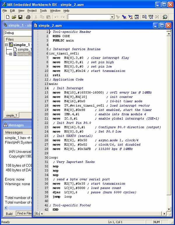
Figure 4. Example application code with interrupt.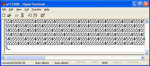
Figure 5. Typical output of the example applications from Figure 4 and Figure 6.
We now follow the same logical steps, but this time using C-syntax for our ISR-function.
Source Identification. We must tell the compiler what module is the source for the interrupt:
#pragma vector=4__interrupt void isr_module4() {}The #pragma directive and keyword __interrupt inform the compiler that the following function (isr_module4() in our example) should be invoked when there is an active interrupt signal from module 4. Because only one source within module 4 is active, no more source identification is needed.
Clear the flag. If we use Timer1 Overflow interrupt, the flag is bit TF2 in the register T2CNB1. Clear it with
T2CNB1_bit.TF2=0; // clear interrupt flag
Note that names TF2 and T2CNB1_bit are merely substitutes for bit 3 and register M4[8], respectively. They are defined in the tool-specific include file "iomaxq200x.h".
Interrupt action. Issue a pulse on the port pin P0.0:
PO0=1;
// set pin highPO0=0;
// set pin low
and send a symbol "$" via the serial port for visualization.
SBUF0='$';
// start transmission
Again, the names are defined in the include file and serve as substitutes for Mxx[yy].
Exit. Nothing to do; the compiler takes care of that.
Similarly, the interrupt initialization code is a direct ASM-to-C translation, except for setting the IV register which is done automatically by the compiler:
Configure Timer1 to overflow every 1ms.
T2R1=65536-16000;
// ovfl every 1ms @ 16MHzT2V1=T2R1;
// init counterT2CFG1=0;
// 16-bit timer mode
Load the IV register with the ISR address—done by the compiler.
Enable Timer1 Overflow interrupt at all three levels: individual, module, and global.
T2CNA1=0x88;
// int enabled, start the timerIMR_bit.IM4=1;
// enable ints from module 4IC_bit.IGE=1;
// enable global interrupts (IGE=1)
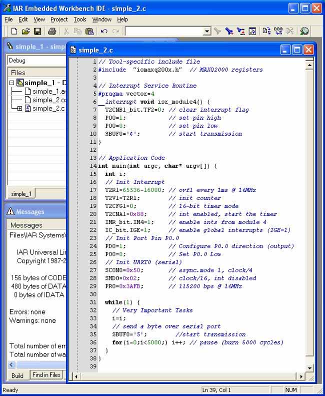
Figure 6. Example application with interrupt in C.
We also must initialize the port pin, i.e. set direction and voltage level:
PD0=1;
// Configure P0.0 direction (output)PO0=0;
// Set P0.0 Low
Assembling all the pieces together we end up with the code presented in Figure 6. When run on hardware, its output looks the same as shown in Figure 5.
Programming Nested Interrupts
Usually, when an interrupt is being serviced, the trigger signal is blocked at the global level by a special bit called INS (not shown in Figure 1). That bit is automatically set by hardware when entering the ISR and cleared when the RETI or POPI instruction is executed (usually when exiting an ISR). No interrupt can be triggered while INS = 1. However, some applications might want to allow nested or recursive interrupts. This can be done by clearing the INS bit inside the ISR, allowing interruption of the interrupt service routine flow. Note that the second interrupt call will be vectored to the same ISR pointed by the IV register as the first one, therefore the application should make provisions against infinite loops when allowing recursive interrupt calls.
Figure 7 shows an application with an interrupt activated on the falling edge of a port pin (connected to a push-button). This application uses the Ext0 interrupt on the MAXQ2000, located in module 0. The push-button is connected to the corresponding port pin P0.4. The interrupt service routine is designed to allow interruption of its own code by clearing the INS bit (line 14 in Figure 7). The intrinsic function __reenable_interrupt() is provided for this purpose, though the same job could be done by writing the bit directly: IC_bit.INS=0;. To prevent an infinite loop, the ISR calculates the level of nesting by incrementing the global variable nest_level on entry and decrementing on exit. The INS bit is cleared only when nesting level does not exceed a certain limit (up to 7 levels are allowed in this example).
While no interrupts happen, the application continuously outputs the character "0" via the serial port, indicating that the main() function is being executed. When the button is pushed, the ISR prints the current nesting level and executes an idle loop for a few more seconds, so the button could be pushed again while the ISR is still running. When the nesting reaches level 7, the INS bit is not cleared any more. If the button is pressed while executing the ISR at level 7, the new interrupt request stays pending (the flag is set but the trigger signal is blocked by INS = 1) until the ISR finishes and exits, clearing the INS bit and resuming the ISR at level 6. Then the pending interrupt becomes active and causes an ISR call at level 7 again. This described behavior is illustrated in Figure 8—each nonzero digit indicates an ISR entry, including recursive interrupt calls.
Programming Interrupt-Priority Schemes
In the MAXQ architecture, such interrupt service ordering must be implemented in software, because no hardware priority exists. In this application note we consider just two of many possible approaches to prioritizing interrupt services:
Source identification ordering (without recursive interrupts)
Dynamic interrupt re-configuration (with recursive interrupts)
In fact, both methods can be mixed together in one application, as we will see in the following example, creating flexible and effective interrupt service structure.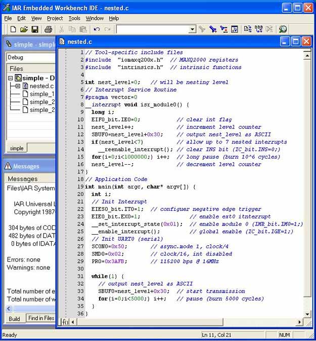
Figure 7. Example application with nested interrupt in C.
The former method implies arranging the source-identification part of the ISR in such a way that higher priority sources are identified and serviced first, before the lower priority sources. For example, assume the three sources in Figure 1 are signaling simultaneously, but the application wants to process the Watchdog interrupt first, then the Timer1 Overflow, and then the UART1 Transmit. The task can be solved by the following pseudo-code:
if (){}if (){}if (){}
This simple technique has almost no overhead; it does not require extra memory or recursive interrupt calls. Each interrupt is executed from start to finish in the order it was received, except when two or more interrupts are pending. In that case, the order of servicing is defined by the source-identification arrangement in the application code. But this method has a drawback: if an urgent, highest priority interrupt occurs when the other source is being serviced, it must wait until the ISR finishes, and by that time it might be too late. To overcome this problem we have to allow interruption of the ISR flow, which brings us to the second method—dynamic interrupt re-configuration.
The latter approach is more general and implies the following steps for each individual ISR:
Save the current interrupt configuration and re-configure the entire set of the enable bits in order to disable all lower (than current) or equal priority sources, but enable higher priority sources
Allow recursive interrupts, i.e., clear the INS bit
Execute the action for the current interrupt
Disallow recursive interrupts, i.e., set the INS bit
Restore saved in step i) interrupt configuration and exit.
This implementation allows a higher priority interrupt to be serviced almost immediately, even if it occurs while a lower priority source is being serviced. However, this method consumes more data and program space, increasing with every extra interrupt source added to the scheme.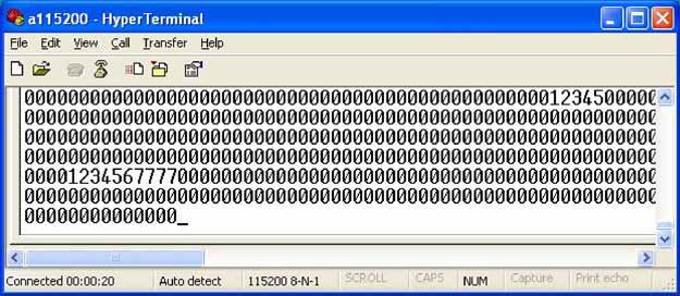
Figure 8. Output of the example application from Figure 7.
To demonstrate both methods, we create an example MAXQ2000 application with the following interrupt priority scheme:
| Interrupt Source | Source Module | Priority | Interrupt Action |
| Watchdog Timer | 7 | 99 (highest) | Clear Watchdog Timer; print a symbol to UART0 |
| UART0 Transmit | 2 | 70 | Transmit next byte from buffer, if any |
| Timer1 Overflow | 4 | 50 | Fire a pulse on the port pin P0.0 (every 128ms) |
| External Int 0 | 0 | 30 | Very important push-button action (red button) |
| External Int 10,11,12 | 1 | 10, 11, 12 | Push-button actions (green buttons) |
The watchdog timer is given the highest priority because it will reset the device if not cleared in time. Then we make use of the UART's transmit interrupt, which signals that a byte has been successfully sent and the next byte transmission can be started. This interrupt is also a high priority to ensure fast communication and prevent the buffer from overflowing. Next comes the Timer1, which fires pulses at a comparatively slow but regular pace. The push-button interrupts are given lower priority because they are coming irregularly.
The modular architecture makes it easy and convenient to assign priority at the module level. In this case, the only configuration data to save/reconfigure/restore is the IMR register, which is the 8-bit module interrupt mask. Otherwise, the entire set of the scattered individual enable bits must be stored, reconfigured, and restored in every individual ISR. Therefore, we implement a general priority approach (dynamic re-configuration) for the modules, but a simple ordering method for interrupt sources within a module.
The module 1 in our example has multiple interrupt sources, and Figure 9 shows how the priority is implemented inside the module 1 interrupt routine isr_module1(). First, it saves the current interrupt configuration (line 39 in Figure 9), then reconfigures interrupts to disable sources in module 1, but enable higher priority modules 0, 4, 2, 7 (line 40), and re-enables interrupts by clearing the INS bit (line 41). Then it identifies and services the interrupt sources within module 1 in the order of their priority. The higher priority int12 is checked first (lines 45-50), the lower priority int11 is checked second (lines 52-57), and the lowest priority int10 is checked last (lines 59-64). The service routines for those interrupts have long delay loops (inside the button() function, lines 48, 55, and 62 in Figure 9), so other interrupts can occur while the interrupt routine isr_module1() is still running.
Other interrupts are designed in similar fashion (see full source code in Appendix A, available for download), except for the highest priority Watchdog interrupt where no re-configuration is needed. The application writes various ASCII marks via UART0 so they can be captured on the PC to visualize the execution flow. For the demonstration, the hardware was assembled with two push-buttons: one connected to the pin P0.4 activating the External Interrupt 0 when pressed; another connected to pins P5.2, P5.3, P6.0 corresponding to the External Interrupts 10, 11, 12, respectively, so all three interrupts get activated simultaneously when that button is pressed down. Since the former interrupt Ext0 has higher priority, we will call it a "red button," while another button will be referred as "green button," activating the three lower priority interrupts.
When no buttons are pressed, the application prints "=Reset=" and then continuously writes the word "Main," dots "..." and the word "

评论