
Choosing the Right RS-232 Tran
Abstract: This arTIcle is intended to help the design engineer sort through the various features available in RS-232 interface products. The main features described are the regulated charge pump, Autoshutdown, RS-232 compaTIble versus compliant operaTIon, ESD protecTIon, and data rates including Megabaud operation.
In 1987, Maxim introduced the MAX232, the first single-supply RS-232 device. The MAX232 (and other single supply devices) includes two charge pumps. The first charge pump doubles +5V to approximately +10V and the second charge pump inverts the +10V charge-pump output to -10V. Since these charge pumps are unregulated, the positive and negative output voltages of the transmitters often drop well below +10V and -10V. The depth of the power supplies drop is a function of both the capacitance of the cable driven by the transmitters and the data rate.
The MAX232 quickly became an industry standard. Many board designers still use the MAX232 today, despite the fact that single-supply devices have undergone extensive improvements over the years. Understanding the features of new devices will help the design engineer choose the best parts for the application.
Questions about noise immunity often arise when design engineers first discover these devices. However the noise immunity of theses devices is excellent, despite the fact that the regulated charge pumps work harder to maintain a ±5.4V output as cables become longer and the capacitive load increases. In fact, the ±5.4V output is better maintained with longer cables at higher data rates with devices that incorporate regulated charge pumps over devices that utilize unregulated charge pumps whose outputs are initially of a higher voltage.
Maxim also offers a series of RS-232 transceivers that operate from voltages as low as 2.35V. Maxim even has two ultra low power supply RS-232 transceiver, the MAX218 and MAX3218, which use an inductor along with capacitors to allow operation with a single +1.8V supply.
Other RS-232 devices incorporate a more advanced feature called Autoshutdown, which typically limits the shutdown supply current to 1uA. These devices can determine whether a transmission cable is attached to the RS-232 transceiver. If a cable is not attached to the RS-232 transceiver, the unit will go into shutdown until the presence of a transmission cable is detected. A transceiver equipped with the Autoshutdown feature monitors the RS-232 signals at its receiver inputs to determine whether a cable is connected. When a cable is not present, the signals at the RS-232 receiver inputs are approximately 0V. If the transceiver detects that all the receiver inputs are between -0.3V and +0.3V for greater than 30µS, it assumes that a valid transmitter cable is not connected and will automatically put itself into a low-power mode (shutdown). The part will automatically take itself out of shutdown if any one of the receiver's inputs exceeds +2.7V (i.e., whenever the cable is reconnected). This feature can be overridden with signals that force the device on or off. See Figure 1. The MAX3228E, MAX3229E and the MAX3246E are three examples of transceivers that incorporate the Autoshutdown feature.
Figure 1. The Autoshutdown Plus logic incorporated in an RS-232 transceiver, allows the transceiver to stay powered on as long it detects signal transactions at its transmitter or receiver inputs within 30-second intervals. Otherwise the transceiver is automatically powered down when the interval between signals is greater than 30 seconds. Logic levels applied to the FORCEON and active-low FORCEOFF inputs turn the device's power on and off overriding the Autoshutdown Plus logic controlled by receiver and transmitter input signal activity.
Autoshutdown Plus is similar to Autoshutdown in that it is designed to save power by shutting down the RS-232 device whenever it is not in use. The Autoshutdown Plus shuts down the transceiver when the cables are disconnected, and when the cable is connected and data edges haven't been detected for 30 seconds or more. This way you can get the benefit of an automated shutdown regardless of whether the cable is connected. Autoshutdown-Plus devices monitor both the RS-232 receiver inputs and the digital transmitter inputs for signal activity; shutdown ensues if no activity is present on any of these lines for 30 seconds. As with Autoshutdown, you can force on or off the device using pins that override the Autoshutdown Plus feature. See Figure 1. The MAX3238E, MAX3380E, MAX3381E, MAX3226E and the MAX3246E are five examples of transceivers that incorporate the Autoshutdown Plus feature.
Some applications require ±15kV ESD protection on both the RS-232 and the CMOS digital terminals. For example, in order to reduce cost and size, cell phones do not include the RS-232 transceiver in the phone itself. Instead CMOS-level signals are routed through the connector at the bottom of the phone. If the cell-phone owner wants to connect to the RS-232 port of a laptop, he or she will purchase a "data-lump" cable, which includes an RS-232 transceiver. In this situation, both sides of the RS-232 transmitters and receivers are brought out to connectors, exposing them to increased ESD risk. In such cases, it may be desirable to have extended ESD protection on both the RS-232 and CMOS sides of the transmitters and receivers. The MAX3237E, MAX3380E and MAX3381E are three examples of transceivers that are suited to this task.
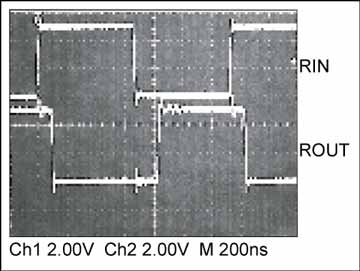
Figure 2. The above oscilloscope photo shows an RS-232 receiver operating at 1Mbps.
A similar version of this article appeared in the March 2003 issue of Electronic Products magazine.

RS-232 Background
Despite the development of newer digital interface standards, the humble RS-232 serial port is still a very popular means of data transfer. Robust and easy to use, the RS-232 interface is still an attractive alternative to the more demanding and temperamental digital interfaces. This application note describes key features and helps the designer choose the right RS-232 transceiver. Factors to consider include:- Power supply requirements
- Power consumption/battery-life features (such as autoshutdown)
- Speed (data rates)
- Compliance with signal level standards
- Enhanced ESD protection
- Isolation features
- Package size
The Single-Supply RS-232 Transceiver
The RS-232 standard requires signal levels of +5V (minimum) for a low and -5V (minimum) for a high. A higher voltage swing ensures greater noise immunity after the signals travel through lossy cables to RS-232 receivers. Early RS-232 transceivers (such as the MAX1488 and MAX3185, which are still in use today) required dual power supplies. Most circuit boards included a negative power supply solely to power these devices.In 1987, Maxim introduced the MAX232, the first single-supply RS-232 device. The MAX232 (and other single supply devices) includes two charge pumps. The first charge pump doubles +5V to approximately +10V and the second charge pump inverts the +10V charge-pump output to -10V. Since these charge pumps are unregulated, the positive and negative output voltages of the transmitters often drop well below +10V and -10V. The depth of the power supplies drop is a function of both the capacitance of the cable driven by the transmitters and the data rate.
The MAX232 quickly became an industry standard. Many board designers still use the MAX232 today, despite the fact that single-supply devices have undergone extensive improvements over the years. Understanding the features of new devices will help the design engineer choose the best parts for the application.
RS-232 Transceivers Powered by Low-Voltage Single Supplies
As power-supply voltages dropped from +5V to +3.3V and lower, single-supply RS-232 transceivers kept pace. The transceivers that are powered from voltages ranging from 3.0V to 5.5V use two regulated charge pumps instead of the unregulated types used in the parts powered by only +5V. Rather than double the input voltage, a single regulated charge pump boosts the input voltage to approximately +5.4V. A second regulated charge pump inverts the +5.4V supply to approximately -5.4V. This constitutes significant power-savings, since it takes less energy to drive the capacitive load of a cable with ±5.4V versus ±10V. Further energy savings is achieved by turning off (skipping cycles) the respective charge pumps once the their target output voltage has been achieved.Questions about noise immunity often arise when design engineers first discover these devices. However the noise immunity of theses devices is excellent, despite the fact that the regulated charge pumps work harder to maintain a ±5.4V output as cables become longer and the capacitive load increases. In fact, the ±5.4V output is better maintained with longer cables at higher data rates with devices that incorporate regulated charge pumps over devices that utilize unregulated charge pumps whose outputs are initially of a higher voltage.
Maxim also offers a series of RS-232 transceivers that operate from voltages as low as 2.35V. Maxim even has two ultra low power supply RS-232 transceiver, the MAX218 and MAX3218, which use an inductor along with capacitors to allow operation with a single +1.8V supply.
Increased Battery Life through Autoshutdown Techniques
Many RS-232 transceivers provide a simple shutdown feature that is activated by applying a logic level to the shutdown pin. Since most RS-232 devices are only used for a short period of time, the shutdown feature can save energy and increase the run-time of portable equipment batteries.Other RS-232 devices incorporate a more advanced feature called Autoshutdown, which typically limits the shutdown supply current to 1uA. These devices can determine whether a transmission cable is attached to the RS-232 transceiver. If a cable is not attached to the RS-232 transceiver, the unit will go into shutdown until the presence of a transmission cable is detected. A transceiver equipped with the Autoshutdown feature monitors the RS-232 signals at its receiver inputs to determine whether a cable is connected. When a cable is not present, the signals at the RS-232 receiver inputs are approximately 0V. If the transceiver detects that all the receiver inputs are between -0.3V and +0.3V for greater than 30µS, it assumes that a valid transmitter cable is not connected and will automatically put itself into a low-power mode (shutdown). The part will automatically take itself out of shutdown if any one of the receiver's inputs exceeds +2.7V (i.e., whenever the cable is reconnected). This feature can be overridden with signals that force the device on or off. See Figure 1. The MAX3228E, MAX3229E and the MAX3246E are three examples of transceivers that incorporate the Autoshutdown feature.
Figure 1. The Autoshutdown Plus logic incorporated in an RS-232 transceiver, allows the transceiver to stay powered on as long it detects signal transactions at its transmitter or receiver inputs within 30-second intervals. Otherwise the transceiver is automatically powered down when the interval between signals is greater than 30 seconds. Logic levels applied to the FORCEON and active-low FORCEOFF inputs turn the device's power on and off overriding the Autoshutdown Plus logic controlled by receiver and transmitter input signal activity.
Autoshutdown Plus is similar to Autoshutdown in that it is designed to save power by shutting down the RS-232 device whenever it is not in use. The Autoshutdown Plus shuts down the transceiver when the cables are disconnected, and when the cable is connected and data edges haven't been detected for 30 seconds or more. This way you can get the benefit of an automated shutdown regardless of whether the cable is connected. Autoshutdown-Plus devices monitor both the RS-232 receiver inputs and the digital transmitter inputs for signal activity; shutdown ensues if no activity is present on any of these lines for 30 seconds. As with Autoshutdown, you can force on or off the device using pins that override the Autoshutdown Plus feature. See Figure 1. The MAX3238E, MAX3380E, MAX3381E, MAX3226E and the MAX3246E are five examples of transceivers that incorporate the Autoshutdown Plus feature.
Compatible Versus Compliant
To be compliant with the RS-232 specification, transmitters are required to provide a ±5V output signal level. For RS-232 receivers to be compliant, their thresholds must be ±3V maximum. Therefore, these devices operate with a healthy ±2V noise margin. Thus it is possible to erode a percentage of the margin and still maintain accurate data transmissions. Margins are reduced when transmitter output voltages span a narrower range. When transmitter outputs are a minimum of ±3.7V, they are considered to be compatible, instead of compliant RS-232 outputs. For example, if you power an RS-232 device that doesn't contain charge pumps (thus less expensive and smaller) with ±5V supplies, its output voltages cannot possibly reach ±5V. A device operated under these conditions with transmitter outputs of ±3.7V at minimum is said to be RS-232 compatible instead of compliant.Enhanced ESD Protection
All RS-232 devices include ESD protection structures on their terminals to protect against electrostatic discharges encountered during handling and assembly. Several manufacturers offer devices with both standard and enhanced protection. Since the standard and the enhanced-protection parts are almost always available with the same pin configuration, adding devices with enhanced ESD protection typically does not require any modifications to an existing PC board.Some applications require ±15kV ESD protection on both the RS-232 and the CMOS digital terminals. For example, in order to reduce cost and size, cell phones do not include the RS-232 transceiver in the phone itself. Instead CMOS-level signals are routed through the connector at the bottom of the phone. If the cell-phone owner wants to connect to the RS-232 port of a laptop, he or she will purchase a "data-lump" cable, which includes an RS-232 transceiver. In this situation, both sides of the RS-232 transmitters and receivers are brought out to connectors, exposing them to increased ESD risk. In such cases, it may be desirable to have extended ESD protection on both the RS-232 and CMOS sides of the transmitters and receivers. The MAX3237E, MAX3380E and MAX3381E are three examples of transceivers that are suited to this task.
Data Rates
The latest RS-232 specification calls for data rates of 20kbps or below. Despite this restriction, the data rates of most RS-232 transceivers far surpass that speed. In fact, today's RS-232 transceivers reach speeds up to 1Mbps. See Figure 2 for an example of a transceiver operating at 1Mbps. To reach such speeds, these devices violate another RS-232 specification, the maximum allowed transmitter-output slew rate of 30V/µs. The RS-232 specification requires that transmitter outputs do not exceed this slew rate, thus reducing the amount of noise generated by fast edges. The outputs of transceivers that operate at speeds of up to 1Mbps are also slew-rate limited, however at a slew rate that exceeds the RS-232 specification. The outputs of these transmitters emit noise at higher frequencies than do their slower-slew-rate counterparts. The faster slew rate of these devices also creates another concern, compatibility with slower devices. If a part capable of Megabit-per-second operation transmits data at high speeds, a transceiver capable of operating at the same speed must be present at the other end of the cable. If a slower speed device is instead used at the other end of the cable, operation at slower data rates will probably work, although not guaranteed. The MAX3227E, MAX3245E and MAX3225E are three examples of transceivers that are capable of 1Mbps transmission rates.Figure 2. The above oscilloscope photo shows an RS-232 receiver operating at 1Mbps.
Isolated RS-232 Transceivers
Maxim created the MAX3250, a +50V isolated transceiver capable of withstanding damage if the transmission lines are inadvertently short-circuited to a +24 or +48V power bus. The MAX3250 is a low cost replacement for opto-isolated transceivers. Maxim's propriety isolation method is inductorless and transformerless simplifying EMI compliance.Package Size
Maxim developed the world's smallest RS-232 receivers and transmitters available in a tiny SOT23-5 package. These parts are optimized for low power space saving applications with shutdown currents as low a 0.2uA. The MAX3189E and the MAX3190E are excellent examples of RS-232 SOT23-5 transmitters with low shutdown current, and are complimented with the MAX3180E family of receivers.A similar version of this article appeared in the March 2003 issue of Electronic Products magazine.

评论