数字脉冲继电器控制开关


(注:文章为软件自动翻译,请读者自行斟酌其意思。)
介绍:
摆在首位,继电器就像一个带开关线圈组件。当给线圈通电时,继电器闭合。当线圈一直通电时,开关一直闭合。
因此,脉冲继电器用它来打开一盏灯的按钮,而不是拨动开关。将它们放置在不同的位置。在一个房间里,我可以打开电灯,并把它关掉,他也可以从不同的房间里控制灯的开关,这就是脉冲继电器的作用。
脉冲继电器是一个完美的电子电路,特殊性在此电路中,它可用于家庭自动化的中央系统。另一个优点是价格较低。数字脉冲继电器抗干扰能力强,按钮和电路之间的连接可以任何长度的非屏蔽线。
工作原理:
该电路的操作房间的照明的基本组成部分是一个IC1(CD4017)。按钮的室连接通常连接到电路。所有的电路是分别由光耦,这意味着电路是免疫电噪声电缆连接按钮,可以来的。
任何按钮,首先推到GND光耦的输出信号被放大晶体管Q1(BC557)一起由C1,R3,R4电路放大后的信号被攻击的时钟引脚14十年柜台IC1(CD4017)计数器前进1,2脚变为高电平,继电器ON晶体管Q2(2N2222)连接到引脚2 IC1驱动12V继电器。二极管1N4004(D1)作为一个续流二极管。LED1显示的ON / OFF状态。
第二次按下任何按钮,IC1的前进1,2脚变为低电平,继电器断开,4脚变为高电平。如果我们连接的二极管D2,引脚4到复位引脚CD4017,计数器会回到初始状态,并准备好另一个按钮,打开继电器。
C2 - R6组件保持复位引脚到+12 V,当电路供电,直到C2加载12V。
从晶体管Q2 colector的是IN / OUT用于单片机系统(GSM远程控制,网络控制等)。当使用为IN,可以把单片机系统到GND Q2 colector,继电器为ON。或colector是作为输出使用,获得的信号说的单片机系统,如果继电器ON或OFF。
该电路的电源电压为直流12V。继电器为OFF时,在待机状态下,数字脉冲继电器消耗0V。否则,当继电器ON,消耗依靠12V继电器电流。
原文:
Introduction
In the first place, a relay is like a switch to a coil assembly. This switch is activated when electricity is applied to the coil. With a common relay, the electricity must be continuously applied to the coil to maintain the contacts, but the impulse relay remembers and only requires a momentary application of electricity. Stated differently, apply pulse of electricity to the coil to turn on the relay contacts, apply another pulse of electricity to turn off the relay contacts.
So, impulse relay use it for to turn on a lamp with pushbuttons and not toggle switches. What is really neat is connecting several momentary pushbuttons in parallel and placing them in different locations. I can turn on the lamp in one room, and turn it off from a different room, because it was the relay that was providing electricity to the lamp, not the switch.
Adigital impulse relayis a electronic circuitthat mimics perfect the all functions of a impulse relaywith ratchet mechanism: the first press to the button turns the relay on and the second press turns it off, andrelay in the circuit operating room illuminates.Particularity of this circuit is that it can be used in a centralized system for home automation. Another advantage is lower price compared with that of theimpulse relaywith ratchet mechanism. Digital impulse relay is immune to electrical noise, connection between buttons and circuit can be achieved with unshielded cable and any length.
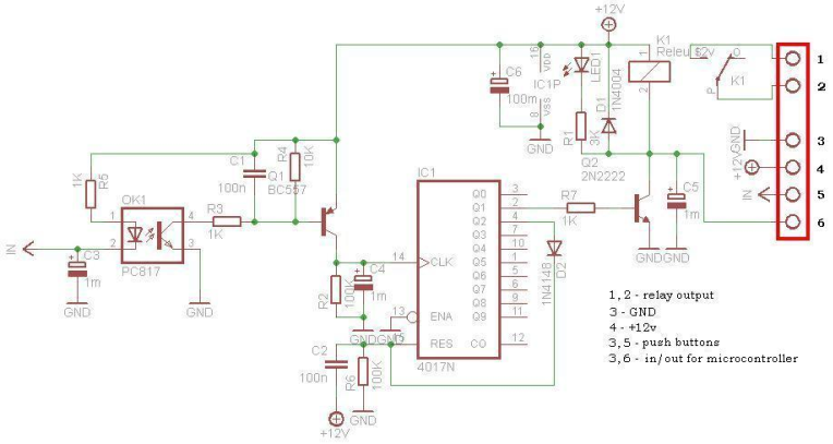
Schematic
This circuit isoperating the room illuminates.Thebasic component of the circuit isa IC1 (CD4017). Push buttons room are connected by normally wired to the circuit. All circuit is separately by optocoupler, which means that the circuit is immune to electrical noise that can come on cable that connects with push buttons.
First any button push put to GND the optocoupler IN.The output signal fromoptocoupleris amplified by transistorQ1 (BC557) together by C1, R3, R4 circuit.The amplified signal isattackto clock pin 14 of decade counterIC1 (CD4017), the counteradvances by 1, pin 2 goes high and relay is ON.Transistor Q2 (2N2222) connected to pin 2 of IC1 drives 12V relay. Diode 1N4004 (D1) acts as a freewheeling diode. LED1indicate the ON/OFF status.
Second any button press, the IC1advances by 1, pin 2 goes low, relay is OFF, and pin 4 goes high. If we connect by diode D2, pin 4 to Reset pin of CD4017, the counter is going back to the initial condition, and is ready to get anotherbuttonpress, to turn the relay ON.
The C2 - R6 component keep the Reset pin to +12V, when the circuit ispowering, until the C2 loaded at 12V.
From transistor Q2 colector is IN/OUT for use in to microcontroller system (GSM remote control, WEB control, etc.). When use as IN, microcontroller system can put to GND Q2 colector, and relay is ON. Or the colector is use as OUT, signal obtained say the microcontroller system, if the relay is ON or OFF.
The power supply for the circuit is DC 12V. In standby, when relay is OFF,digital impulse relay consume 0V. Otherwise,when relay is ON, consume depend of 12V relay current.
电路原理图
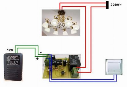
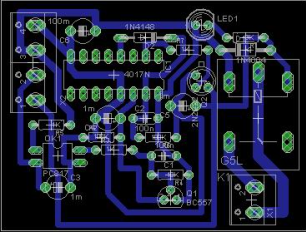
安装图
元件清单
元件清单:
IC1 - CD4017
Q1 - BC557
Q2 - 2N2222
OK1 - PC817(光耦)
D1 - 1N4004
1N4148 D2 -
R1 -
R23 K- 100 K
R3 -
R41 K- 10 K
R5 - 1 K
R6 - 100 K
R7 - 1 K
C1 - 100 nF的
C2 - 100 nF的
С3 - 1 uF/25V
С4 - 1 uF/25V
С5 - 1 uF/25V
С6 - 1 uF/25V
LED1 -二极管
K1 - 12V继电器
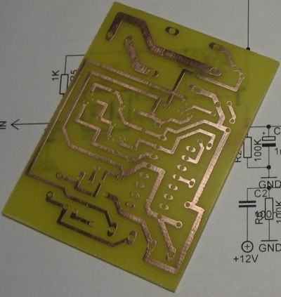
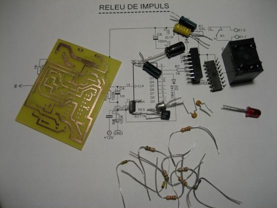
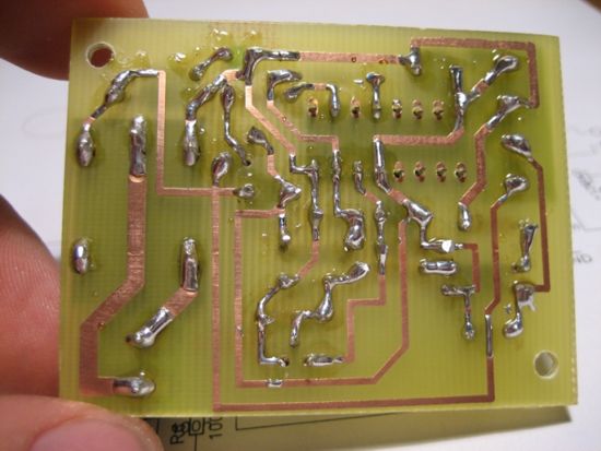
PCB电路板
PCB图
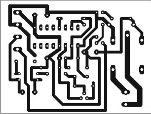
PCB图
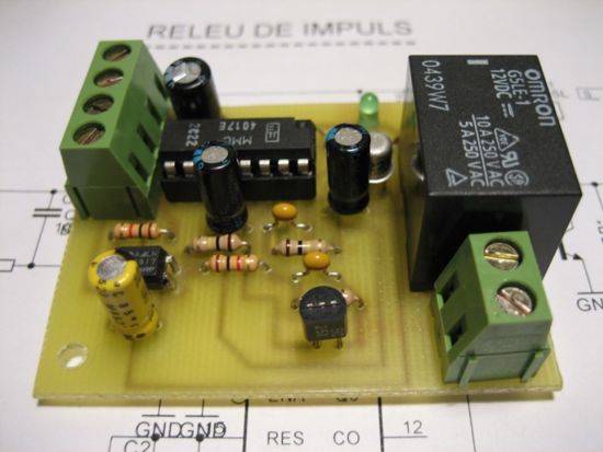
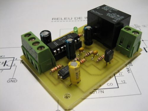
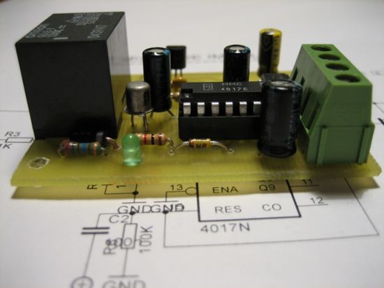
实物图
技术资讯 技术方案 技术应用 技术新品 技术前沿 行业资讯 行业方案 行业应用 行业新品 行业前沿
评论