
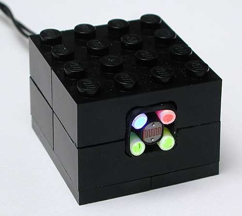
颜色传感器的制作

 电路分析:(说明:内容为软件自动翻译,请自行理解其意思。)
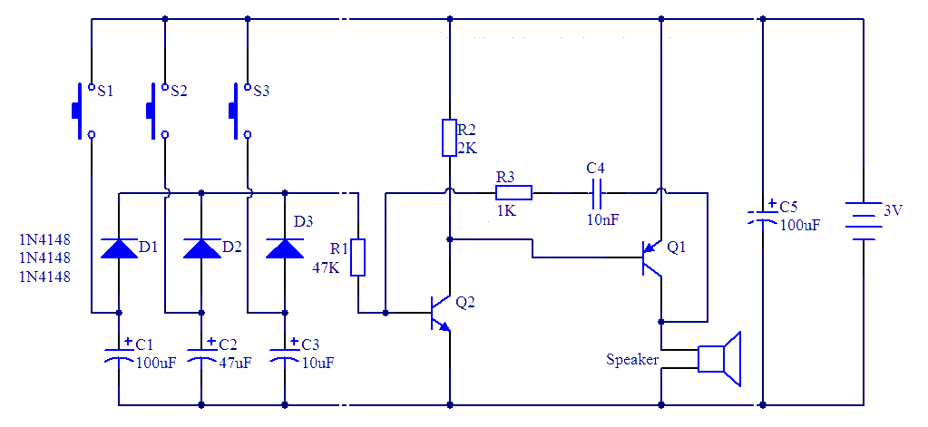
该电路的心脏是一个CD4017CMOS计数器。在每个脉冲上收到它的时钟输入,IC驱动高输出(所有其他驱动为低电平),输出0,1和2个驱动器的红色,绿色和蓝色LED,通过晶体管Q2,Q3,Q4(使用射极跟随器基极电阻,以避免需要)。前三阶段,输出4拉低,光敏电阻器R8提供接地参考:RCX可以读取光的水平,反映在每种颜色。在第4阶段不再光敏电阻接地,返回值RCX是最大(注意1毫欧电阻并联与R8防止最大值到达阶段1/2/3)。RCX可以检测到这种特殊条件和同步读数CD4017状态。
硬拷贝示波器显示时钟脉冲的顶部曲线,下面的输出1/2/3。产生一个时钟脉冲,你必须在有源传感器模式(传感器电压高于齐纳二极管D4门槛切换时,Q1导通,时钟输入低)被动传感器模式(传感器电压低比D4门槛,Q1被封锁,时钟输入高)和有源传感器。C1过滤掉短脉冲电源在主动模式下埃维3ms的发生RCX读取值。
示波器的硬拷贝显示时钟脉冲的顶部曲线,底部跟踪显示2短脉冲和广泛的指令脉冲所产生的传感器模式切换传感器上的电压,当到达第5步,CD4017激活D04,并自行复位通过第1阶段R4/C3。这RC网络的延迟后复位脉冲时钟过渡:没有它,目前急于通过电源的LED,再加修改时钟阈值和CD4017直接进入第2步...
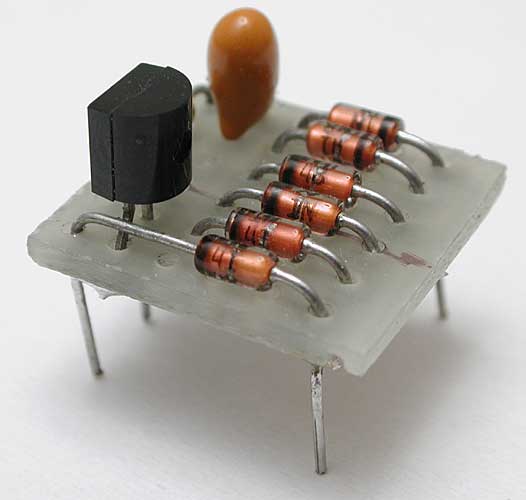
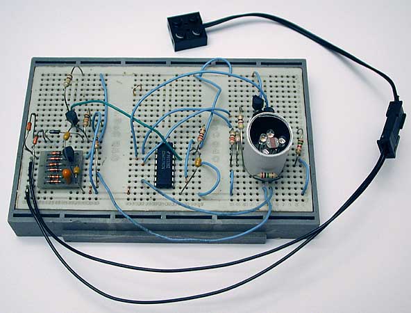
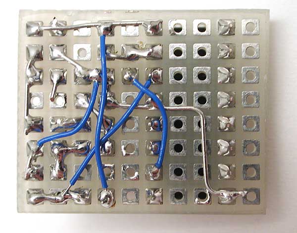
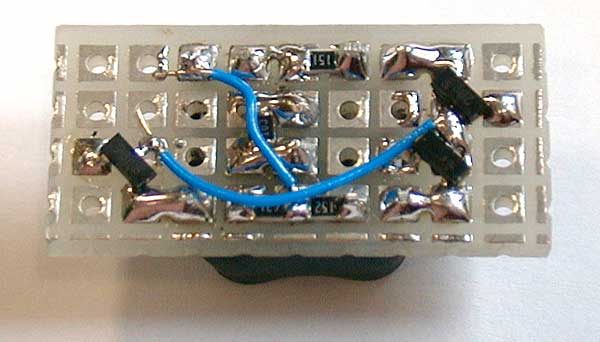
电源整流D1和C2滤波。至于我在其他的传感器,我保持单二极管,而不是全桥,以减少元件数量(3个二极管,而不是8!),但你可以看到,我建了面包板采用了全桥模块构造,以减轻我的原型。
原文:
Circuit analysis
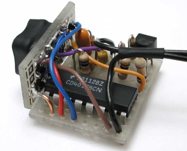
The heart of this circuit is a CD4017 (IC1), CMOS counter with decoded output. On each pulse received on its clock input, this IC drives high the next output (all the other are driven low).
Output 0, 1 and 2 drives red, green and blue LEDs through transistors Q2, Q3, Q4 (emitter follower is used to avoid the need of a base resistor). During the first three phases, output 4 is driven low and provide ground reference for photo-resistor R8: the RCX can read light level reflected in each color. In phase 4 photo-resistor is no longer grounded, value returned to RCX is maximum (note the 1 Mohm resistor paralleled with R8 to prevent maximum value to be reached in phases 1/2/3). RCX can detect this special condition and synchronize its readings to CD4017 state.
The oscilloscope hard-copy shows clock pulse on top trace, output 1/2/3 below.
To generate a clock pulse, you have to switch from active sensor mode (sensor voltage is higher than Zener D4 threshold, Q1 is conducting, clock input is low) to passive sensor mode (sensor voltage is lower than D4 threshold, Q1 is blocked, clock input is high) and back to active sensor. C1 filters out short power supply pulses occuring in active mode evey 3ms while RCX reads value.
The oscilloscope hard-copy shows clock pulse on top trace, sensor voltage on bottom trace showing 2 short reading pulses and wide command pulse generated by sensor mode switching.
Power supply is rectified by D1 and filtered by C2. As in my other sensors, I keep on with single diode instead of full bridge to minimize components count (3 diodes instead of 8!) but as you can see I built the breadboard with a full bridge module I constructed to ease my prototypes.
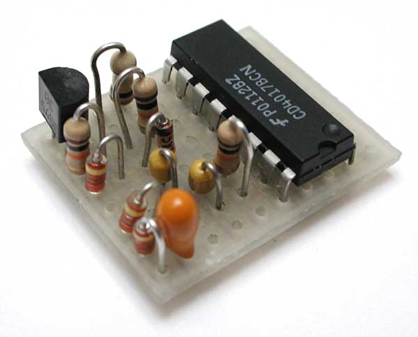
Component selection
Nothing is really critical: D1 to D3 are small signal diodes (i.e. 1N4148), Q1 to Q4 are general purpose NPN transistors (BC548, 2N2222...). Photo-resistor I used is aMPY54C569(any similar size LDR will probably work fine). Leds are high efficiency 3mm ones. I used Agilent: redHLMP-K105for D5, blueHLMP-KB45for D8, greenHLMP-1540for D6 and D7. I was somewhat disappointed by green Leds efficiency. Though the photoresistor has its peak sensitivity around green wavelength, read value was fairly low with green lighting. After testing different Led types and brands, I finally chose to use two green leds with maximum current. Even then color sensor sometimes has troubles to distinguish between green and black (!) Lego bricks... Green bricks reflects surprisingly very little light, I guess the problem is that my green leds have a too yellowish wavelength. Most of the components were bought fromFarnell.
Led current is limited by R5, R6 and R7. To set their values, I placed the breadboard in front of a white piece of paper and adjusted them to get about the same reading for all colors.

技术资讯 技术方案 技术应用 技术新品 技术前沿 行业资讯 行业方案 行业应用 行业新品 行业前沿
评论