NXP LPC54102传感器处理和运动解决方案
NXP公司的LPC5410x系列MCU具有超低功耗性能,双处理器内核ARM Cortex-M4和 ARM Cortex-M0+,最大工作频率100 MHz,适用于传感器任务如听,采集和聚集传感器数据以及如传感器融合的复杂传感器处理任务.主要用在手机和平板电脑,手持健身和保健监视, 智能传感, 家庭和建筑物自动化(HABA),车(船)队管理和资产跟踪,机器人和无人驾驶飞机,游戏附件等.本文介绍了LPC54102主要特性和优势,框图,传感器处理/运动解决方案主要特性如开发板和传感器屏蔽板电路图和PCB元件布局图.
The LPC54100 Series microcontrollers were designed from the ground up to deliver the industry’s best power efficiency for always-on sensor-processing applications. These highly efficient MCUs support ultra-low-power performance for sensor tasks such as listening, collection, and aggregation of sensor data as well as complex sensor processing tasks such as sensor fusion.
Crucial for always-on applications, LPC54100 Series MCUs require as little as 3 µA for continuous sensor listening. A first for sensor applications, an asymmetric dual-core architecture enables scalable active power/performance: Developers can use the 55 µA/MHz Cortex-M0+ core for sensor data collection, aggregation, and external communications, or the Cortex-M4F core (100 µA/MHz) to execute math-intensive algorithms (i.e., motion sensor fusion) more quickly while saving power. The LPC54100 Series also includes single-core (Cortex-M4F) options with similar sensor listening and M4F power efficiencies.
This architecture is complemented by a range of analog and digital interfaces designed for power efficiency — including a 12-bit, 4.8 Msps ADC capable of full-spec performance at the full voltage range, as well as low-power serial interfaces. Together these features enable LPC54100 Series MCUs to offer the best overall power efficiency for sensor processing than any other microcontrollers in their class.
For fast development, NXP offers the LPCXpresso54102 board for rapid prototyping and evaluation and an application-in-a-box LPC54102 Sensor Processing/Motion Solution to bring sensor-based motion and other sensor-processing applications to market quickly.
LPC54102主要特性和优势:
Dual processor cores: ARM Cortex-M4 and ARM Cortex-M0+. The M0+ core runs at the same frequency as the M4 core. Both cores operate up to a maximum frequency of 100 MHz.
ARM Cortex-M4F core (version r0p1):
ARM Cortex-M4 processor, running at a frequency of up to 100 MHz.
Floating Point Unit (FPU) and Memory Protection Unit (MPU).
ARM Cortex-M4 built-in Nested Vectored Interrupt Controller (NVIC).
Non-maskable Interrupt (NMI) input with a selection of sources.
Serial Wire Debug with eight breakpoints and four watch points.
Includes Serial Wire Output for enhanced debug capabilities.
System tick timer.
ARM Cortex-M0+ core (version r0p1):
ARM Cortex-M0+ processor, running at a frequency of up to 100 MHz.
ARM Cortex-M0+ built-in Nested Vectored Interrupt Controller (NVIC).
Non-maskable Interrupt (NMI) input with a selection of sources.
Serial Wire Debug with four breakpoints and two watch points.
System tick timer.
On-chip memory:
Up to 512 KB on-chip flash program memory with flash accelerator and 256 byte page erase and write.
104 KB SRAM for code and data use.
ROM API support:
Flash In-Application Programming (IAP) and In-System Programming (ISP).
Power control API.
Serial interfaces:
Four USART interfaces with synchronous mode and 32 kHz mode for wake-up from Deep-sleep and Power-down modes. The USARTs include a FIFO buffer and share a fractional baud-rate generator.
Two SPI interfaces, each with four slave selects and flexible data configuration.
The SPIs include a FIFO buffer. The slave function is able to wake up the device from Deep-sleep and Power-down modes.
Three I2C-bus interfaces supporting fast mode and Fast-mode Plus with data rates of up to 1Mbit/s and with multiple address recognition and monitor mode. Each I2C-bus interface also supports High Speed Mode (3.4 Mbit/s) as a slave. The slave function is able to wake up the device from Deep-sleep and Power-down modes.
Digital peripherals:
DMA controller with 22 channels and 20 programmable triggers, able to access all memories and DMA-capable peripherals.
Up to 50 General-Purpose Input/Output (GPIO) pins. Most GPIOs have configurable pull-up/pull-down resistors, programmable open-drain mode, and input/output inverter.
GPIO registers are located on the AHB for fast access. The DMA supports GPIO ports.
Up to eight GPIOs can be selected as pin interrupts (PINT), triggered by rising,falling or both input edges.
Two GPIO grouped interrupts (GINT) enable an interrupt based on a logical (AND/OR) combination of input states.
CRC engine.
Timers:
Five 32-bit general purpose timers/counters, with up to 4 capture inputs and 4 compare outputs, PWM mode, and external count input. Specific timer events can be selected to generate DMA requests.
One State Configurable Timer/PWM (SCT) with 6 input and 8 output functions
(including capture and match). Inputs and outputs can be routed to/from external pins and internally to/from selected peripherals. Internally, the SCT supports 13 captures/matches, 13 events and 13 states.
32-bit Real-time clock (RTC) with 1 s resolution running in the always-on power domain. A timer in the RTC can be used for wake-up from all low power modes including Deep power-down, with 1 ms resolution. The RTC is clocked by the 32 kHz oscillator.
Multiple-channel multi-rate 24-bit timer (MRT) for repetitive interrupt generation at up to four programmable, fixed rates.
Windowed Watchdog Timer (WWDT).
Ultra-low power Micro-tick Timer, running from the Watchdog oscillator,that can beused to wake up the device from low power modes.
Repetitive Interrupt Timer (RIT) for debug time-stamping and general-purpose use.
Analog peripheral: 12-bit, 12-channel, Analog-to-Digital Converter (ADC) supporting 4.8 Msamples/s. The ADC supports two independent conversion sequences.
Clock generation:
12 MHz internal RC oscillator.
External clock input for clock frequencies of up to 24 MHz.
Internal low-power, watchdog oscillator with a nominal frequency of 500 kHz (WDOSC).
32 kHz low-power RTC oscillator.
System PLL allows CPU operation up to the maximum CPU rate. May be run from the internal RC oscillator, the external clock input CLKIN, or the RTC oscillator.
Clock output function for monitoring internal clocks.
Frequency measurement unit for measuring the frequency of any on-chip or off-chip clock signal.
Power-saving modes and wake-up:
Integrated PMU (Power Management Unit) to minimize power consumption.
Reduced power modes: Sleep, Deep-sleep, Power-down, and Deep power-down.
Wake-up from Deep-sleep and Power-down modes via activity on the USART, SPI,and I2C peripherals.
Wake-up from Sleep, Deep-sleep, Power-down, and Deep power-down modes using the RTC alarm.
The Micro-tick Timer can wake-up the device from the Deep power-down mode by using the watchdog oscillator when no other on-chip resources are running.
Single power supply 1.62 V to 3.6 V.
Power-On Reset (POR).
Brown-Out Detect (BOD) with separate thresholds for interrupt and forced reset.
JTAG boundary scan supported.
Unique device serial number for identification.
Operating temperature range 40 ℃ to 105 ℃.
Available in a 3.288 x 3.288 mm WLCSP49 package and LQFP64 package.
LPC54102主要应用:
Mobile handsets & tablets
Portable fitness & health monitoring
Intelligent sensing
Home and building automation (HABA)
Fleet management & asset tracking
Robotics & drones
Gaming accessories
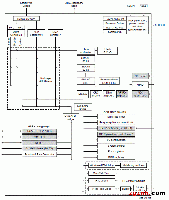
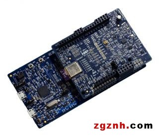
图2. LPCX54102传感器处理/运动解决方案外形图
LPCX54102传感器处理/运动解决方案主要特性:
LPC54102 MCU in an LQFP64 package
Built-in Link2 high-speed USB based debug probe and option for an external debug probe
Tri-color LED, target Reset, ISP and WAKE buttons
On-board regulators for 1.8 V or 3.3 V supply or external power supply options
Built-in MCU power consumption, sensor board and supply voltage measurement
UART, I²C and SPI port bridging from LPC54102 target to USB via Link2 device
Sensor Shield Board Bosch Sensortec sensors: BMI055 inertial measurement unit BMC150 digital compass, BMM150 magnetometer and BMP280 pressure/temperature sensor
Murata ZPA2326 pressure sensor
MAX44000 ambient light and proximity sensor
ACKme AMS0002 Bluetooth LE module
IR remote control transmitter/receiver
Dual Knowles digital microphones
Headers for easy prototyping of additional SPI and I²C sensors
Supported by NXP Sensor Framework and Bosch Sensortec BSX Lite sensor fusion library, available for free download at www.lpcware.com (subject to license terms and conditions)
LPCX54102传感器处理/运动解决方案包括:
LPC54102 Development Board
Sensor Shield Board
Micro USB cable
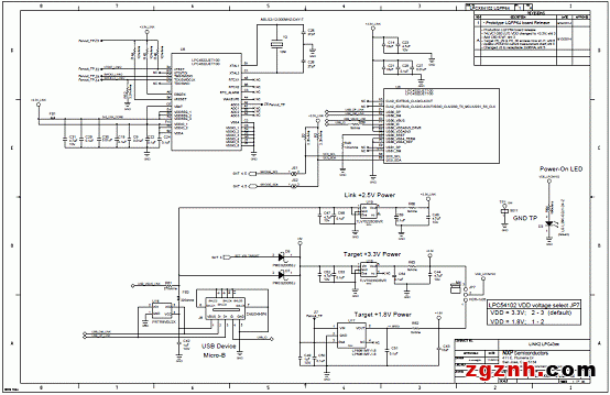
图3. LPC54102开发板电路图(1)
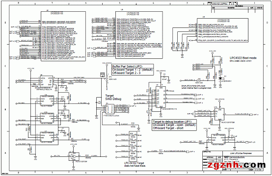
图4. LPC54102开发板电路图(2)
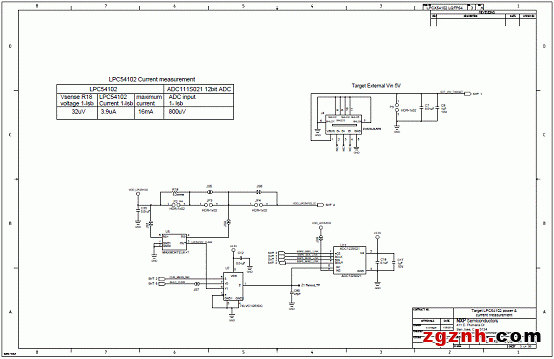
图5. LPC54102开发板电路图(3)
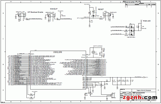
图6. LPC54102开发板电路图(4)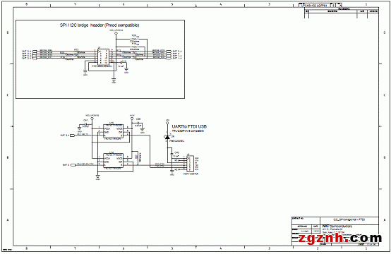
图7. LPC54102开发板电路图(5)
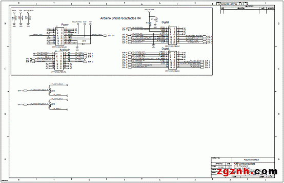
图8. LPC54102开发板电路图(6)
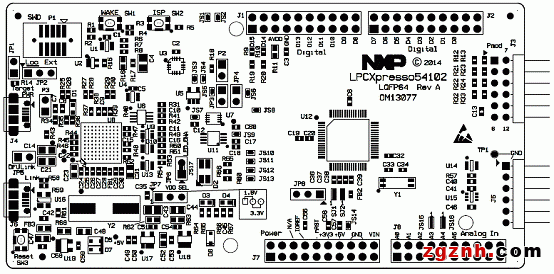
图9. LPC54102开发板PCB元件布局图:顶层
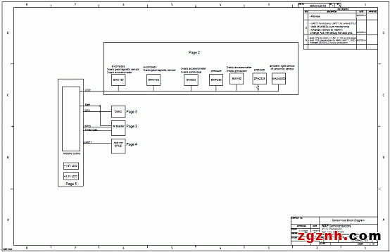
图10. LPC54102传感器屏蔽板电路图(1)
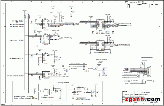
图11. LPC54102传感器屏蔽板电路图(2)
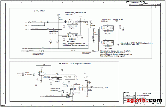
图12. LPC54102传感器屏蔽板电路图(3)
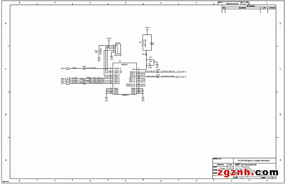
图13. LPC54102传感器屏蔽板电路图(4)
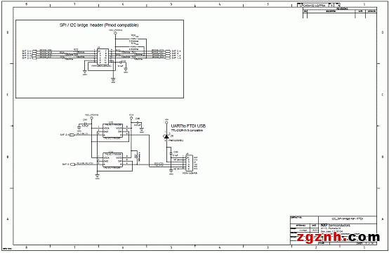
图14. LPC54102传感器屏蔽板电路图(5)
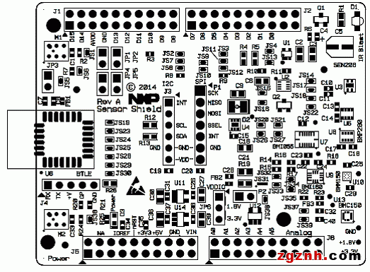
图15. LPC54102传感器屏蔽板元件布局图:顶层


评论