
LED应用中,LED电路的形式,及电阻的计算-----LED applications and circuit calculation method

LED照明行业是一个新兴的行业,它以其独特的优点深受人们的青睐。如今在光电工程中,提高光效,节约能源和高可靠性已经成为人们共同追求的目的。我们在讨论和使用LED光源时,都会想到LED的寿命长、节约能源、亮度高等特点。也正是因为如此LED光源才倍受欢迎。LED光源虽有以上优点,却并不如人们所说的那么神奇。只有给其配上合适、高效的LED电源、合理的电路设计、完善的防静电措施、正确的安装工艺才能充分发挥和利用LED光源的以上优点。下面我就LED光源在工程应用中的一些常识做简单的介绍,供大家参考。
LED的使用寿命,一般认为在理想状态下有10万小时。实际在使用过程中其光强会随使用时间的推移逐渐衰减,即电能转化为光能的效率逐渐降低。我们能真正使用的有效光强范围应在其衰减到初始光强的70%以上时,寿命是否可以定义为光效逐渐降低至70%的时间段。目前还没有明确的国家标准用来衡量。而且LED的使用寿命与其芯片的质量和封装技术、工艺直接相关,据某LED封装厂的试验数据有些芯片在20mA条件下连续点亮4000小时后其光亮度衰减已达50%。但是随着技术、工艺的提高,光衰时间越来越缓慢,即寿命也越长。
LED是电流控制元件,通过流过的电流,直接将电能转变为光能,故也称光电转换器。因其不存在摩擦损耗和机械损耗,所以在节能方面比一般的光源的效率高,但是LED光源并不能像一般的普通光源一样可以直接使用电网电压,它必须配置一个电压转换装置,提供满足其额定的电压、电流,才能正常使用,即LED专用电源。但是各种不同的LED电源其性能和转换效率各不相同,所以选择合适、高效的LED专用电源,才能真正体现LED光源高效特性。因为低效率的LED电源本身就需要消耗大量电能,在配合LED的使用过程中根本就体现不出LED的高效节能特性。而且LED电源也必须是高可靠性电源,才能使LED光源系统长寿命。
四、LED的基本特性及使用时的注意事项
1.光电特性:
LED在其电流极限参数范围内流过LED的电流越大,它的发光亮度越高。即LED的亮度与通过LED的电流成正比。但绿光和蓝光及白光在大电流情况下会出现饱和现象,不仅发光效率大幅降低,而且使用寿命也会缩短。
2. 光学特性
LED按颜色分有红、橙、黄、绿、蓝、紫、白等多种颜色。按亮度分有普亮、高亮、超高亮等,同种芯片在不同的封装方式下,它的亮度也不相同。按人的视觉可分为可见光和不可见光。按发光颜色的多少可分为单色、双色、七彩等多种类型。色彩的纯度不同价格相差很大,现行的纯白色LED价格特贵。同时发光视角不同,光效亦不同,使用时特需注意。
3.常见的LED电性能参数
(1)LED正向电压
不同颜色的LED在额定的正向电流条件下,有着各自不同的正向压降值,红、黄色:1.8~2.5V之间,绿色和蓝色:2.7~4.0V之间。对于同种颜色的LED,其正向压降和光强也不是完全一致的。如下表:
LED 型号:5 4HCA
发光颜色 外观颜色 波长λD(nm) 正向电压VF 亮度Iv(mcd)
IF=20mA
Min. Max.
红色 水透明 620~6451.8 2.2500~10000
黄色 水透明 585~595 1.8 2.2 500~10000
蓝色 水透明455~4753.03.4 500~10000
绿色 水透明515~535 3.03.42000~20000
蓝绿色 水透明 490~515 3.03.4 2000~20000
白色 水透明 3.03.43000~25000
在同一电路中应该尽量使用在额定电流条件下正向压降值相同、光强范围小的LED。只有这样才能保证LED的发光效果一致。其具体的电性参数可依各封装厂每包装提供的产品分光参数标签值。(有些公司每批分选都不一致)
(2)LED的额定工作电流
LED的额定电流各不相同,普通的LED电流一般为20mA,大功率的LED电流一般为40 mA 或350 mA不等。具体要按各封装厂提供的电流参数值。
一般LED在反向电压:VR=5V的条件下,反向电流:IR≤10μA。
(3)LED的功率
LED功率的大小也各不相同,有70mW、 100mW、 1W、2W、3W、5W等,
所以必须根据所选择的LED,设计合理的使用电路和配置合适的LED数量,使其完全满足LED电源的额定值,如果设计的电路使每个LED分担电压或电流过高就会严重影响LED的使用寿命甚至烧毁LED,如果分担的电压或电流过低则激发的LED光强不够,就不能充分发挥LED应有的效果,达不到我们所期望的目的。
4. 温度特性
(1)LED的焊接温度应在250℃以下,焊接时间控制在3~5S之间。要注意避免LED温度过高从而使芯片受损。
(2)LED的亮度输出与温度成反比,温度不仅影响LED的亮度,也影响它的寿命。使用中尽量减少电路发热,并做一定的散热处理。
5. 防静电特性
LED装配过程中必须加强防静电措施,因为操作过程和人体本身都会产生静电,对于双电极的LED最易被静电反向击穿,从而严重影响LED的使用寿命甚至使其完全报废。
如防静电环境不是非常完善,可以给LED使用者增加防静电腕带,设置良好的防静电接地系统,离子风机等设备。
五、LED连接电路的常见形式
1.串联:这种电路需要电源提供较高的电压。
V总=各LED的VF之和=VF1+VF2+VF 3+VF 4------+VF N
I总=单颗LED的IF值
2. 并联:这种电路需要电源能提供较高的电流。
V总=单颗LED的VF 值
I总=各LED的IF之和=IF1+IF2+IF3+IF4------+IFN
3. 串联/并联组合
a、 在实际运用中,负载常采用通过串并联形成的LED阵列;
b、 将LED连接成串联/并联组合的形式,可大幅减低因少数LED的VF不一致造成的影响;
c、 阵列形式或LED个数变化,限流电阻也应相应变化。
d、 串联/并联组合的形式会使输出电流随输入电压和环境温度等因素而发生的变化更加显著;
4. 为了能有效控制电路中的电流,须在电路中配置适当的限流电阻。
R=(V输入电压-VLED总电压)/I(流过限流电阻的电流)
限流电阻的作用主要是控制LED的电流,使电压更平滑,并使各并联支路的亮度更均匀。限流电阻阻值大效果较好,但是限流电阻的取值也不能太大,否则会增加电能的损耗及元件温度升高。
1、按驱动方式可分为两大类:
(1)恒流式:
a、 恒流驱动电路输出的电流是恒定的,而输出的直流电压却随着负载阻值的大小不同在一定范围内变化,负载阻值小,输出电压就低,负载阻值越大,输出电压也就越高;
b、 恒流电路不怕负载短路,但严禁负载完全开路。
c、 恒流驱动电路驱动LED是较为理想的,但相对而言价格较高。
d、 应注意所使用最大承受电流及电压值,它限制了LED的使用数量;
(2)稳压式:
a、 当稳压电路中的各项参数确定以后,输出的电压是固定的,而输出的电流却随着负载的增减而变化;
b、 稳压电路不怕负载开路,但严禁负载完全短路。
c、 以稳压驱动电路驱动LED,每串需要加上合适的电阻方可使每串LED显示亮度平均;
d、 亮度会受整流而来的电压变化影响。
2、按电路结构方式分类
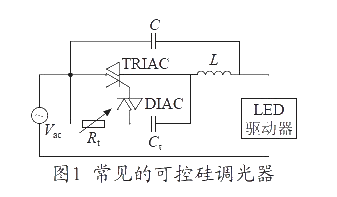
(1)电阻、电容降压方式:通过电容降压,在闪动使用时,由于充放电的作用,通过LED的瞬间电流极大,容易损坏芯片。易受电网电压波动的影响,电源效率低、可靠性低。(见图一)
(2)电阻降压方式:通过电阻降压,受电网电压变化的干扰较大,不容易做成稳压电源,降压电阻要消耗很大部分的能量,所以这种供电方式电源效率很低,而且系统的可靠也较低。(见图二)
(3)常规变压器降压方式:电源体积小、重量偏重、电源效率也很低、一般只有45%~60%,所以一般很少用,可靠性不高。
(4)电子变压器降压方式:电源效率较低,电压范围也不宽,一般180~240V,波纹干扰大。
(5)RCC降压方式开关电源:稳压范围比较宽、电源效率比较高,一般可以做到70%~80%,应用也较广。由于这种控制方式的振荡频率是不连续,开关频率不容易控制,负载电压波纹系数也比较大,异常负载适应性差。
(6)PWM控制方式开关电源:主要由四部分组成,输入整流滤波部分、输出整流滤波部分、PWM稳压控制部分、开关能量转换部分。PWM开关稳压的基本工作原理就是在输入电压、内部参数及外接负载变化的情况下,控制电路通过被控制信号与基准信号的差值进行闭环反馈,调节主电路开关器件导通的脉冲宽度,使得开关电源的输出电压或电流稳定(即相应稳压电源或恒流电源)。电源效率极高,一般可以做到80%~90%,输出电压、电流稳定。一般这种电路都有完善的保护措施,属高可靠性电源。
从以上介绍可以看出PWM控制方式设计的LED电源是比较理想的LED电源。目前珠海市南宇星电子公司生产的“金兴”牌LED开关电源就是PWM控制技术的开关电源,该类LED电源经用户使用反映效果很好。
七、工程中的简易计算方法
1. 由已知电源功率计算LED的数量
(即取所得数据的整数) (7-1)
例:额定输出功率为10W电源,使用额定的正向电流20mA,耗散功率为70mW条件下可配置多少个LED?
依以上公式
(即取所得数据的整数)
2. 对于恒压驱动方式:由已知的输出电源电压计算每支路串联LED数量及并联支路数
(1)计算每条支路的LED个数 公式: (最大值)
(2)计算并联支路数 公式:
注:VLED值依不同发光颜色各有不同,用稳压电源驱动LED时,为了控制电流,通常需要串联电阻器。
例:一个额定输出电压为DC 24V,功率为10W电源,使用额定正向电流20mA,耗散功率为70mW额定的正向电压为1.8V。可配置多少个LED呢?
依以上公式可以得出
(即取所得数据的整数)
即可以带10组支路,每支路14个LED串联构成的电路,共140个LED。
3. 对于恒流驱动方式:由已知的电源输出电流及LED的电流值计算出并联支路数及每支路数量
(1)计算并联的支路数公式: (最小值)
(2)计算支路串接LED个数:
注:其中n按(7-1)计算
例:一个额定输出电流为DC 0.35A,额定功率为10W电源,驱动耗散功率为70mW,正向电流为0.02A的LED,可怎样配置?
依以上公式可以得出
并联支数路:
(即取所得数据的整数)
每支路串接数:个数
即可以带17组,每组8个LED串接,共136个LED。
4. 线路损耗及线路压降的计算
P电线=I R V电线=IR
R电线=σ (备注:L为电线长度;S为电线横截面积;σ为电线电导率)也可以查电工手册。
例:用长度为10米(正、负极电线各5米),24AWG的铜芯电线,通过电流为2A,其损耗的功率及线路压降为多少?
查电工手册可知:R电线 = 0.737W
V电线 = 2×0.737 =1.474V
P电线 = 2 ×0.737 = 2.948W
从以上计算可以看出,线路电流较大时,要注意选择合适的导线截面,否则线路损耗及线路压降是相当大的。
我们只有完全了解LED和LED电源的基本特性,才能正确设计和使用LED光源。
GOOGLE TRANSLATE
Introduction of LED light source applications:
LED lighting industry is an emerging industry, it is by the people for its unique advantages of all ages. Today in the optical engineering to improve lighting efficiency, energy saving and high reliability has become a common pursuit of purpose. We are in discussions and use of LED light source, will think of LED's long life, energy saving, high brightness characteristics. Is precisely because of this LED light source was popular. Despite these advantages LED light source, but not as it says it is magic. Only to its coupled with appropriate, efficient LED power supply, reasonable circuit design, improved anti-static measures, proper installation and use of technology to give full play to advantages of LED light source above. Here I LED light source applications in the works of some common sense to do a brief introduction for your reference.
2, LED life understanding
LED life is generally believed that under ideal conditions, 10 million hours. Actually in the course of its intensity with the use of the gradual decay over time, that the efficiency of light energy into electrical energy decreases. We can really use the effective range of light intensity should be in its decay to the initial light intensity of 70% or more, life is defined as the luminous efficiency can be gradually reduced to 70% of the time. There is no clear national standards to measure. LED chip life and its quality and packaging technology, process is directly related to LED packaging factory, according to a test data under some chips 20mA continuous light, after 4000 hours the brightness of its light attenuation reached 50%. But with the technology, process improvement, light failure time is slow, that is, the longer life expectancy.
3, LED energy-saving and reliability
LED is a current control element, by the current flowing through directly to electrical energy into light energy, it also called electron converter. Does not exist because of friction losses and mechanical losses, so energy saving light source than the average efficiency, but the LED light source and not as an ordinary light source can be directly used as grid voltage, it must configure a voltage converter to provide meet rated voltage, current, to the normal use, the LED Power Supply. However, a variety of LED power conversion efficiency of its performance and different, so choose a suitable and efficient LED dedicated power supply, can only truly efficient LED light source characteristics. Because of the low efficiency of LED power supply itself consumes a lot of power, with LED's used in the process of not simply reflect the high efficiency LED power-saving features. And the LED power supply must also be highly reliable power supply, can the long-life LED light source system.
4, LED's basic features and use precautions
1. Optical characteristics:
LED in its current limits within the parameters of the current flowing through LED larger, the higher its brightness. The LED's brightness is proportional to the current through the LED. But the green and blue and white situation in the high current saturation phenomenon occurs not only significant reduction in luminous efficiency, and life will become shorter.
2. Optical properties
LED divided by the color red, orange, yellow, green, blue, purple, white and other colors. Brightness divided by general light, bright, super bright, etc., the same kind of chips in different packages, it is not the same brightness. By human vision can be divided into visible and invisible light. According to the number of luminous color can be divided into monochrome, color, colorful and many other types. The purity of color vary widely different prices, the current pure white LED at a price you. At the same time emitting different perspectives, have different optical effects, especially should pay attention when using.
3. Common parameters of the electrical properties of LED
(1) LED forward voltage
Different colors of LED forward current at rated conditions, with their different forward voltage drop value, red, yellow: 1.8 ~ 2.5V, between green and blue: 2.7 ~ 4.0V between. For the same color LED, the forward voltage drop and the light intensity is not entirely consistent. The following table:
LED type: 5 4HCA
Color Appearance Color LED wavelength λD (nm) Forward Voltage VF intensity Iv (mcd)
IF = 20mA
Min. Max.
Red water transparency 1.8 2.2 500 620 ~ 645 ~ 10000
Transparent yellow-green water, 570 ~ 575 1.8 2.2 500 ~ 3000
Transparent yellow water 1.8 2.2 500 585 ~ 595 ~ 10000
Transparent Blue Water 475 3.0 3.4 455 ~ 500 ~ 10000
Transparent green water 515 ~ 535 3.0 3.4 2000 ~ 20000
Transparent blue-green water, 490 ~ 515 3.0 3.4 2000 ~ 20000
White water transparency 3.0 3.4 3000 ~ 25000
In the same circuit should make full use of the forward voltage drop under rated current value of the same intensity range of small LED. The only way to ensure consistent LED glow. Its specific electrical properties we can also provide various packaging factory packaging products for each spectral parameter tag value. (Some companies are inconsistent with each batch of separation)
(2) LED's rated current
The rated current of LED vary the LED current is usually normal 20mA, high-power LED current is typically 40 mA or 350 mA range. According to the packaging factory to provide the specific current parameter values.
General LED in the reverse voltage: VR = 5V conditions, the reverse current: IR ≤ 10μA.
(3) LED power
The size of LED power is also different, with 70mW, 100mW, 1W, 2W, 3W, 5W, etc.
Must be chosen according to the LED, designed to use and configure the appropriate LED circuit the number of LED power supply to fully meet the ratings, if the circuit design so that each LED would be too high voltage or current-sharing seriously affect the LED's life or even burning LED, if the share of low voltage or current excitation of the LED light intensity is not enough, we can not give full play to the effect of LED should not reach our expectations purpose.
4. Temperature characteristics
(1) LED soldering temperature should be below 250 ℃, welding time control between the 3 ~ 5S. LED temperature is too high to be taken to avoid damage to the chip.
(2) LED's light output with temperature is inversely proportional to the temperature not only affects the LED's brightness, but also affect its life. To minimize the use of the circuit, fever, and do some heat treatment.
5. Anti-static properties
LED assembly process must strengthen the anti-static measures, and the human body because the operation will have a static, two-electrode of the LED for the most vulnerable to static reverse breakdown, which seriously affect the service life of LED and even make it completely scrapped.
Such as anti-static environment is not very well, can give the user increased anti-static wrist strap LED, set a good anti-static grounding system, ion blower and other equipment.
5, LED connection circuit of the common forms of
1. Series: This circuit requires a higher voltage power supply.
V total = the sum of the LED's VF = VF1 + VF2 + VF 3 + VF 4 ------+ VF N
I total = the value of single LED's IF
2. Parallel: This circuit requires a power supply can provide higher current.
V = total value of single LED of the VF
I total = sum of all LED's IF = IF1 + IF2 + IF3 + IF4 ------ + IFN
3. Series / parallel combinations
a, in practice, the load is often used by the formation of series-parallel LED array;
b, the LED connected in series / parallel combinations of forms, can be significantly reduced due to a small number of LED's VF inconsistent impact;
c, the number of changes in array form, or LED, current limiting resistor should be changed accordingly.
d, series / parallel combination will form the output current with input voltage and ambient temperature changes and other factors more significant;
4. In order to effectively control the circuit current in the circuit configuration to be the appropriate current limiting resistor.
R = (V input voltage-VLED total voltage) / I (flow through the current limiting resistor)
The main function of the current limiting resistor to control LED current, the voltage is more smooth, and to the parallel branch is more uniform brightness. Limiting resistor big is better, but the values of the current limiting resistor can not be too much, otherwise it will increase the power loss and component temperature.
6, the power of the classification and characteristics
1, by driving mode can be divided into two main categories:
(1) Constant Current:
a, constant current drive circuit output current is constant, while the output DC voltage is different as the size of the load resistance varies within a certain range, the load resistance is small, the output voltage is low, the greater the load resistance, output the higher voltage;
b, constant fear load short circuit, but the non-load fully open.
c, constant current drive circuits to drive the LED is ideal, but relatively higher prices.
d, should be noted that the use of the maximum withstand current and voltage, it limits the number of LED's use;
(2) Regulators type:
a, when the regulator to determine the parameters of the circuit after the output voltage is fixed, while the output current but increase or decrease with load change;
b, open circuit voltage regulator circuits are not afraid of the load, but completely short-circuit the load is strictly prohibited.
c, regulator drive circuit to drive LED, each with an appropriate resistor string needs to be the average brightness of each string of LED display;
d, the brightness will come by the rectifier voltage change.
2, the circuit structure by way of classification
(1) resistor, capacitor step-down way: through the capacitor step-down, when used in the flashing, because the role of charge and discharge, the instantaneous current through the LED extremely easy to damage the chip. Vulnerable to grid voltage fluctuations, power efficiency is low, low reliability. (See Figure 1)
(2) resistance step-down way: through the resistance of blood pressure, interference by the larger power grid voltage, regulated power supply is not easily made, step-down resistor to consume very much energy, so this power supply power supply efficiency is low, and the reliability of the systems are also low. (See Figure 2)
(3) conventional transformer step-down approach: power small, too much weight, power efficiency is very low, only 45% to 60%, so seldom used, reliability is not high.
(4) Electronic transformer step-down approach: power efficiency in low voltage range is not wide, generally 180 ~ 240V, wave interference of.
(5) RCC buck mode switching power supply: voltage range is wide, more efficient power supplies in general can do 70% to 80%, applications are wider. As the oscillation frequency of this control method is not continuous, the switch frequency is not easy to control, the load voltage ripple coefficient is relatively large, abnormal loads and less adaptable.
(6) PWM control mode power supply: mainly composed of four parts, input rectifier filter section, some of the output rectifier, PWM regulator control part, switching power conversion section. PWM switching regulator is the basic working principle of the input voltage, the internal parameters and external load changes, the control circuit is controlled by the difference between signal and reference signal for closed-loop feedback, adjust the primary circuit switching devices turn the pulse width, makes the switching power supply's output voltage or current stable (ie the corresponding power supply or a constant current power supply). High power efficiency, the general can do 80% to 90%, the output voltage and current stability. This circuit has a good general protection measures, is a highly reliable power supply.
As can be seen from the above description is designed PWM control mode LED power supply LED power supply is ideal. Currently Zhuhai South Yuxing Electronics Company production of "King Xing" brand is the LED switching power supply switching power supply PWM control techniques, such LED power by users to reflect good results.
7, the simplified calculation method works
1. By a known amount of power supply LED power calculation
(Ie take the data of the integers) (7-1)
Example: Rated output power 10W power supply, use the rated forward current of 20mA, 70mW power dissipation can be configured under the conditions of the number of LED?
According to the formula above
(That is, the data obtained integer)
2. For the constant drive mode: from the known output voltage LED calculating the number of each road series and parallel circuit number
(1) calculation formula for each branch of the LED Number: (max.)
(2) The formula for calculating the number of parallel branch:
Note: VLED values according to different colors in different light, LED driver with regulated power supply, in order to control the current, usually in series resistor.
Example: a rated output voltage of DC 24V, 10W power supply, use the rated forward current of 20mA, 70mW power dissipation rating of the forward voltage of 1.8V. How many LED can be configured to do?
According to the above formula can be drawn
(That is, the data obtained integer)
10 groups that can take the slip road, each road 14 LED series circuit consisting of a total of 140 LED.
3. For the constant current drive mode: from the known power supply output current and the LED's current value and the number of parallel branch number of each road
(1) formula for calculating the number of parallel branch: (minimum)
(2) calculating the number of slip cascading LED:
Note: where n according to (7-1) calculated
Example: A rated output current of DC 0.35A, 10W rated power, drive power dissipation of 70mW, forward current of 0.02A of the LED, can be how to configure?
According to the above formula can be drawn
Road parallel count:
(That is, the data obtained integer)
Each road series with a few: the number of
That can bring 17 groups of eight LED connected in series, a total of 136 LED.
4. Line loss and line pressure drop calculation
P wire = I R V = IR wire
R cable = σ (Note: L for the cable length; S was wire cross-sectional area; σ over electrical conductivity) can also check electrical manual.
Example: with a length of 10 meters (positive and negative wires each 5 meters), 24AWG the copper wires, through the current of 2A, the loss of power and line pressure drop as much?
Charles Electrical Manual known: R wire = 0.737W
V wire = 2 × 0.737 = 1.474V
P wires = 2 × 0.737 = 2.948W
As can be seen from the above calculation, the line current is high, pay attention to choose the right wire section, or line loss and line voltage drop is considerable.
Only when we fully understand the power LED and LED's basic characteristics, to properly design and use of LED light sources.
评论