Ratiometric Design Overcomes t


Ratiometric Design Overcomes the 25% Tolerance of a Digital Potentiometer
| Bill Laumeister |
| Abstract: This application note explains how to eliminate the voltage change when a digital potentiometer is used as a voltage-divider in series with other resistors.EM> This application note discusses a ratiometric method to convert that resistance tolerance into an acceptable current change. The proposed design also effectively removes the voltage change. In the circuit presented here the voltage output depends only on the ratio of the steps of the pot. The temperature coefficient is better controlled in the design. Ratiometric Method for the DesignThe design challenge is straightforward: a variable voltage between 3V and 4.5V with a tolerance of 3%. Start with the schematic in Figure 1 and do the math. The digital pot is 50kΩ (25% tolerance); R1 is 16.5K (1%) and R2 is 100K (1%). The 25% tolerance of the pot's end-to-end resistance will dominate in this design. 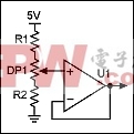 Figure 1. Basic schematic. Now consider the same design with a different pot. If the pot is 37.5kΩ, the top of the pot is 4.46V and the bottom is 3.25V. Continuing on, if the pot is 62.5kΩ, the top of the pot is 4.54V and the bottom is 2.79V. This basic approach does not solve the changing voltage problem because the pot's end-to-end tolerance is in the circuit. The next circuit in Figure 2 only uses the pot's ratio. 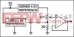 Figure 2. Alternate design features two voltage references. By using two voltage references the tolerances and the temperature coefficient are controlled. The absolute end-to-end tolerance of the digital pot changes the current, but does not affect the voltage. The output voltage is ratiometric; the voltage out depends only on the ratio of the steps of the pot. Both references use feedback to control the output voltage. R2 (~25K to 50K) ensures that both references source current. Bypass capacitors are discussed in the data sheet for each Maxim digital pot. Some capacitors may be required, depending on the board layout. Ultimately, an application dictates the system's requirements. Device temperature coefficients can be predicted from the respective digital pot data sheets. The pots also offer a choice of noise specifications. Maxim's complete list of digital pots and voltage references is available on the website. |
评论