NXP LPC111x 32位MCU马达驱动方案


NXP公司的LPC1110/11/12/13/14/15是基于ARM Cortex-M0内核的32位低成本MCU,提供性能,低功耗和简单指令集和存储器,和现有的8/16位MCU相比,能降低代码大小.CPU工作频率高达50MHz,主要用在马达控制,家用电器,照明,白色家电,计量表和告警系统.本文介绍了LPC111x系列主要特性和优势,框图,LPCXpresso基板和目标板特性和电路图.
The LPC1110/11/12/13/14/15 are an ARM Cortex-M0 based, low-cost 32-bit MCU family,designed for 8/16-bit microcontroller applications, offering performance, low power, simple instruction set and memory addressing together with reduced code size compared to existing 8/16-bit architectures.
The LPC1110/11/12/13/14/15 operate at CPU frequencies of up to 50 MHz.
The peripheral complement of the LPC1110/11/12/13/14/15 includes up to 64 kB of flash memory, up to 8 kB of data memory, one Fast-mode Plus I2C-bus interface, one RS-485/EIA-485 UART, up to two SPI interfaces with SSP features, four general purpose counter/timers, a 10-bit ADC, and up to 42 general purpose I/O pins.
LPC111x系列主要特性和优势:
System:
ARM Cortex-M0 processor, running at frequencies of up to 50 MHz.
ARM Cortex-M0 built-in Nested Vectored Interrupt Controller (NVIC).
Non-Maskable Interrupt (NMI) input selectable from several input sources(LPC1100XL series only).
Serial Wire Debug.
System tick timer.
Memory:
64 kB (LPC1115), 56 kB (LPC1114/333), 48 kB (LPC1114/323), 32 kB
(LPC1114/102/201/202/203/301/302/303), 24 kB (LPC1113), 16 kB (LPC1112),8 kB (LPC1111), or 4 kB (LPC1110) on-chip flash programming memory.
256 byte page erase function (LPC1100XL series only)
8 kB, 4 kB, 2 kB, or 1 kB SRAM.
In-System Programming (ISP) and In-Application Programming (IAP) via on-chipbootloader software.
Digital peripherals:
Up to 42 General Purpose I/O (GPIO) pins with configurable pull-up/pull-downresistors. In addition, a configurable open-drain mode is supported on theLPC1100L and LPC1100XL series.
GPIO pins can be used as edge and level sensitive interrupt sources.
High-current output driver (20 mA) on one pin.
High-current sink drivers (20 mA) on two I2C-bus pins in Fast-mode Plus (not on LPC1112FDH20/102).
Four general purpose counter/timers with up to eight capture inputs and up to 13 match outputs.
Programmable WatchDog Timer (WDT) the LPC1100 series only.
Programmable windowed WDT on the LPC1100L and LPC1100XL series only.
Analog peripherals:
10-bit ADC with input multiplexing among 5, 6, or 8 pins depending on package size.
Serial interfaces:
UART with fractional baud rate generation, internal FIFO, and RS-485 support.
Two SPI controllers with SSP features and with FIFO and multi-protocolcapabilities (second SPI on LPC1100 and LPC1100L series LQFP48 packageonly).
I2C-bus interface supporting full I2C-bus specification and Fast-mode Plus with a data rate of 1 Mbit/s with multiple address recognition and monitor mode (not onLPC1112FDH20/102).
Clock generation:
12 MHz internal RC oscillator trimmed to 1 % accuracy that can optionally be used as a system clock.
Crystal oscillator with an operating range of 1 MHz to 25 MHz.
Programmable watchdog oscillator with a frequency range of 9.4 kHz to 2.3 MHz.
PLL allows CPU operation up to the maximum CPU rate without the need for a high-frequency crystal. May be run from the system oscillator or the internal RCoscillator.
Clock output function with divider that can reflect the system oscillator clock, IRCclock,CPU clock, and the Watchdog clock.
Power control:
Integrated PMU (Power Management Unit) to minimize power consumption during Sleep, Deep-sleep, and Deep power-down modes.
Power profiles residing in boot ROM allowing to optimize performance andminimize power consumption for any given application through one simple functioncall.(LPC1100L and LPC1100XL series only.)
Three reduced power modes: Sleep, Deep-sleep, and Deep power-down.
Processor wake-up from Deep-sleep mode via a dedicated start logic using up to13 of the functional pins.
Power-On Reset (POR).
Brownout detect with up to four separate thresholds for interrupt and forced reset.
Unique device serial number for identification.
Single power supply (1.8 V to 3.6 V).
Available as LQFP48 package, HVQFN33 package, and TFBGA48 package.
LPC1100L series available as TSSOP28 package, DIP28 package, TSSOP20
package, and SO20 package.
Extended temperature (40 C to +105 C) for selected parts
LPC111x应用:
eMetering
Lighting
Alarm systems
White goods

图1.LPC1100/PC1100L系列框图

图2. LPC1100XL系列框图
LPCXpresso目标板
The LPCXpresso target board, jointly developed by NXP, Code Red Technologies, and Embedded Artists (http://www.embeddedartists.com/products/lpcxpresso/), includes an integrated JTAG debugger (LPC-Link), so there’s no need for a separate JTAG debug probe. The target portion of the board can connect to expansion boards to provide a greater variety of interfaces, and I/O devices. The on-board LPC-Link debugger provides a high-speed USB to JTAG/SWD interface to the IDE and it can be connected to other debug targets such as a customer prototype. Users can also use the LPCXpresso IDE with the Red Probe JTAG adapter from Code Red Technologies.
Supported LPC products and board part numbers on the LPCXpresso platform:
• LPC800: All part types supported − OM13053: LPC812
• LPC1100: All part types supported − OM13014: LPC11U14
− OM13012: LPC11C24
− OM13035: LPC1115
− OM13047: LPC1104
• LPC1200: All part types supported − OM13008: LPC1227
• LPC1300: All part types supported − OM13045: LPC1347
• LPC1700: All part types supported − OM13000: LPC1769
• LPC1800: All part types supported
• LPC2000: LPC2109, LPC2109/01, LPC2134, LPC2142, LPC2362, LPC2929
• LPC3000: LPC3130, LPC3250
• LPC4000: All part types supported
LPCXpresso基板
The LPCXpresso Base board makes it possible for you to get started with experiments and prototyping immediately. The Base board can also be used together with the mbed module.
LPCXpresso base board products:
• OM11083: Embedded Artists Base Board for LPCXpresso and mbed
• OM13009: Embedded Artists Motor Control Kit for LPCXpresso
• OM13016: NGX mbed-LPCXpresso baseboard

图3.LPCXpresso开发板外形图
LPCXpresso开发板特性:
Digital I/O
Analog I/O
Serial Bus - SPI
Serial Bus - I²C
Serial Bus - SPI/I²C shared
Serial Bus - UART
Specific LPC1768 (inclmbed) support
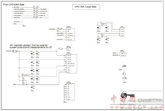
图4.LPCXpresso LPC1769目标板电路图(1)

图5.LPCXpresso LPC1769目标板电路图(2)
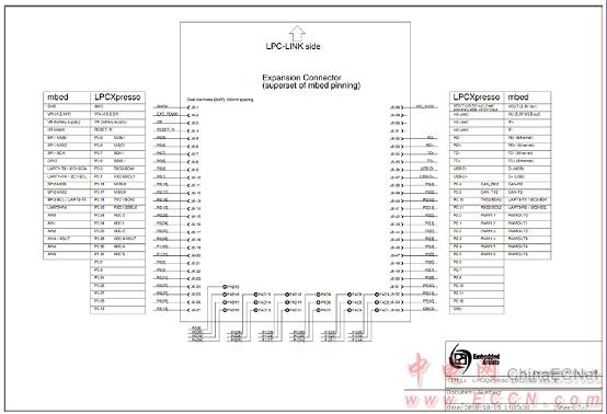
图6.LPCXpresso LPC1769目标板电路图(3)

图7.LPCXpresso LPC1114/LPC1115目标板电路图
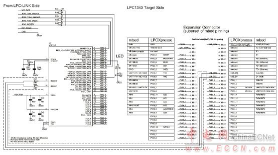
图8.LPCXpresso LPC1343目标板电路图

图9.LPCXpresso LPC11C24目标板电路图(1)
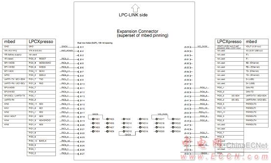
图10.LPCXpresso LPC11C24目标板电路图(2)

图11.LPCXpresso LPC1200目标板电路图(1)

图12.LPCXpresso LPC1200目标板电路图(2)

图13.LPCXpresso LPC11U14目标板电路图(1)

图14.LPCXpresso LPC11U14目标板电路图(2)

图15.LPCXpresso LPC1104目标板电路图(1)
图16.LPCXpresso LPC1104目标板电路图(2)
图17.LPCXpresso LPC800目标板电路图
评论