Time Delay Relay-----延时继电器


When activated by pressing a button, this time delay relay will activate a load after a specified amount of time. This time is adjustable to whatever you want simply by changing the value of a resistor and/or capacitor. The current capacity of the circuit is only limited by what kind of relay you decide to use.
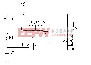
Circuit diagram
Parts:
C1 See Notes
R1 See Notes
D1 1N914 Diode
U1 4011 CMOS NAND Gate IC
K1 6V Relay
S1 Normally Open Push Button Switch
MISC Board, Wire, Socket For U1
C1 See Notes
R1 See Notes
D1 1N914 Diode
U1 4011 CMOS NAND Gate IC
K1 6V Relay
S1 Normally Open Push Button Switch
MISC Board, Wire, Socket For U1
Notes:
1. Email jawaharlal@excite.com with comments, questions, etc.
2. To calculate the time delay, use the equation R1 * C1 * 0.85=T, where R1 is the value of R1 in Ohms, C1 is the value of C1 in uF, and T is the time delay in seconds.
3. S1 may be replaced with an NPN transistor so the circuit can be triggered by a computer, other circuits, etc.
4. Most any 6V relay will work for K1. If you use a large relay, you my need to add a transistor to the output of the circuit in order to drive the larger load.
Author:
Email: jawaharlal@excite.com
Email: jawaharlal@excite.com
评论