多路输出直流稳压电源电路图(Multiple Voltage Power Supply)


多路输出直流稳压电源电路图(Multiple Voltage Power Supply)
下图是一采用三端稳压器的多路输出直流稳压电源电路图。可同时输出正负12V,正负5V。
Figure 1. Circuit Diagram for a +/-12V / +/-5V Power Supply.This is a power supply circuit that provides +12V, -12V, +5V, and -5V regulated outputs. This is just a more complex derivative of a basic negative/positive voltage supply.
Two separate sets of transformer and diode bridge are used to generate the +/-12V and the +/-5V, but the rectification circuits are almost identical. The only difference is the voltage regulator IC's used. The 7812 and 7912 are used to regulate the +12V and -12V outputs, respectively. The 7805 and 7905, on the other hand, are used to regulate the +5V and -5V outputs, respectively. Note that these voltage regulator IC's need to be attached to adequate heat sinks if used in applications that require high power. 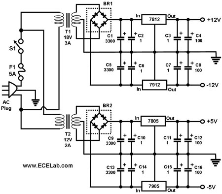
评论