汽车线性稳压器静态电流最小化-Automotive Line


Abstract: Many automotive mechanical functions have been replaced or amended by electronic circuits in recent years. One consequence has been a rapid increase in the number of microcontrollers per car, producing a similar increase in the total current drawn from the car battery. As long the car motor is running and the alternator is operating properly, this power consumption is not a concern.
When you turn off the motor, however, the car battery must immediately deliver all currents demanded by the various subsystems: windshield wiper-blade motors, window lifters, radio/CD player/stereos, and any of the "comfort electronics systems" now found in most cars. Even when all passengers have left the car, many systems draw a keep-alive current to be ready for wake-up when their service is next required. Keeping these quiescent currents as low as possible requires linear regulators with low quiescent current as well as combinations of linear and switch-mode regulators. This article discusses the problem of minimizing quiescent current and introduces some solutions.
The car battery can deliver all the power required—for a while! An average car battery's key specification is its capacity, measured in ampere-hours (Ah). For compact cars, a typical battery provides about 50Ah. In theory, that means that you can draw 1A for 50 hours. Doubling the current reduces the time to half. Starting the car, for example, takes several hundreds of amperes, but only for a short time. Assuming an average current draw of 300A during starting, you should have exactly ten minutes to start the engine before exhausting the battery.
Another example is lighting. Normally, a car has two front bulbs at 50W each and two rear bulbs at 20W each. Together, they consume about 140W. If you forget to switch them off when you leave the car, they will draw about 11.5A from an average 12V system. Assuming the battery is fully charged, you should have four hours before the lights extinguish automatically! In practice, the lights will extinguish earlier than that, and you will not have the ten minutes mentioned above for starting the engine either.
Typical car batteries have only 36Ah to 100Ah of capacity, depending on the car size and type. Several effects reduce the available capacity of a car battery. Colder outside temperatures, for instance, slow the internal chemical reactions. Only half the original capacity is available at -20°C. Older car batteries have less available capacity, and the battery in a car driven repeatedly for short distances (as for running errands in a town) discharges much more rapidly than that of a car used predominantly for long-distance driving. (Normally, a car must be driven for at least half an hour to recharge its full capacity.) The number of charging cycles is approximately 500 for a car that repeatedly discharges its battery by only 30%. Thus, short trips exhaust a battery more quickly and shorten its lifetime. You should expect to replace your car battery every five years.
Depending on the manufacturers and on the total number of such nodes, all these separate small quiescent currents can sum to several milliamps, or perhaps as much as 100mA of continuous current from the battery. Now, consider again the car at the airport: cold weather, city traffic, and age had possibly already reduced the available capacity to the half its nominal value. Thus the battery had only 25Ah left when the car was parked. Given a continuous quiescent current of only 25mA, the capacity lost over 21 days is 12.6Ah. As that amount is removed from the battery just while it is parked, the remainder of battery capacity is reduced to a quarter of the original value. The resulting capacity might not be enough to start a cold motor!
Because the alternator's control loop is not fast enough to close, it generates a high output-voltage pulse when the battery voltage is removed. This high-energy pulse is normally clamped to a lower voltage at some central location in the car, but car manufacturers also specify to their suppliers the remaining overvoltage to be expected at the inputs of their power supplies. This spec differs among car manufacturers, but the typical peak value is 36V in cars and 58V in trucks. Some values are even higher. The duration of a typical load-dump pulse is several tenths of a second (Figure 1).
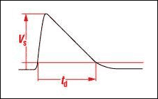
Figure 1. This typical load-dump overvoltage pulse reaches a maximum amplitude (Vs) of 36V in cars and 58V in trucks. Its duration (td) is several hundred milliseconds.
All packages derate their power-dissipation capability with increasing temperature, so that amount of dissipation could become a problem at higher temperatures. A regulator IC in a regular SO8 package would quickly go into thermal shutdown. The regulator would survive and resume operation after it cooled down, but that does not help because we need to keep the function alive. Automotive linear regulators need advanced packages capable of high power dissipation.
A standard automotive linear regulator like the MAX5084 is designed to operate over the automotive temperature range. It has a 65V input range, 50µA typical quiescent current, and a guaranteed output current of 200mA. Its 6-pin TDFN package with exposed pad is capable of 1.9W continuous power dissipation at +70°C, but (as for all packages) that capability is derated at higher temperatures (Figure 2). At +125°C, this package is still capable of dissipating more power than does the standard SO8 package at room temperature. Additional device features include a Kelvin-sense option that controls the output voltage directly at the load, a SET pin that programs output voltages other than the standard 3.3V and 5V, and an Enable function. If the standby function is not needed, you can disable the device which lowers the typical supply current to 6µA.
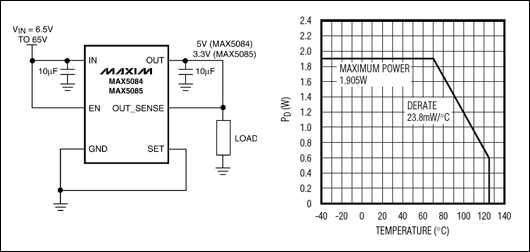
Figure 2. This small but powerful automotive linear regulator comes in a 6-pin TDFN package, and can dissipate up to 1.9W. At the maximum-allowed ambient temperature (+125°C) it can dissipate 600mW.
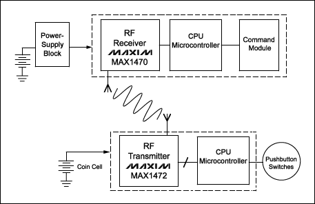
Figure 3. A typical RKE system consists of the car-mounted side and the key-mounted side. Because the car's power supply block connects directly to the battery, its quiescent current must be low.
We must, therefore, optimize the power supply block (top left corner) in terms of minimizing quiescent current. Aside from low quiescent current, requirements on the internal linear regulator are not very stringent. It must simply provide an input, an output, and a ground pin. Shutdown and Enable functions are not required because the receiver is always powered. But, we must look closely at the way it sets the output voltage. Many linear regulators set the output voltage using an external resistor-divider, but that is probably not a good idea for this application. Consider the following scenario.
The MAX1470 RF receiver operates on a 3.3V supply. To ensure its low quiescent current we cannot allow a significant bias current in the resistor-divider. For a maximum current of 2µA, the divider resistance must be no less than 1.65MΩ. That value is available in a chip resistor, but high values have other drawbacks. They make the divider sensitive to distortion that could influence the linear regulator's output voltage.
Another major objection to the use of external resistor-dividers is that car manufacturers anticipate the long-term deposit of a parasitic dirt layer formed by oil, dirt, dust, evaporated plastic, and other particles on the PCB. Thus, the high impedance of the divider tends to decrease over time, as the parasitic layer forms parallel resistances. Direct consequences of this contamination are a slow but continuous change in the output voltage, and a steadily increasing quiescent current. Fixed-output linear regulators containing an internal divider are therefore preferred.
Given these considerations, the MAX15006 linear regulator is a good choice (Figure 4). Its small 6-pin TDFN package is capable of dissipating 1.5W, and it comes with a fixed output voltage of either 3.3V or 5V (other voltages are available upon request). The MAX15006's input voltage range (to 40V, max) allows a direct connection to the car battery, but the main advantage is an ultra-low no-load quiescent current of 9.5µA typical. For a 1mA load, the maximum quiescent current over the automotive temperature range is only 19µA, increasing to 110µA at the maximum load current of 50mA. This performance is acceptable, because the maximum supply current for the MAX1470 receiver in our example is well below 10mA.
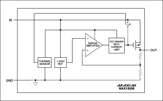
Figure 4. This automotive linear regulator requires a minimum number of pins and external components, minimal board space, and a minimum (typical) no-load supply current of 9.5µA.
A linear regulator with 13V nominal input voltage can, therefore, dissipate 1.2W, and that level can rise briefly to 4W during a load dump. To handle the nominal 26V found in a truck, the regulator must dissipate more than 3W continuously. For these applications, another automotive linear regulator (MAX5087) has been designed for output currents as large as 400mA. It also comes in a larger 8mm x 8mm, 56-pin QFN package that boosts the allowable power dissipation to 3.8W (Figure 5).
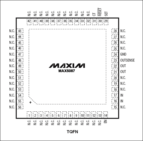
Figure 5. One package option for the MAX5087 linear regulator is a 56-pin QFN, which increases its maximum allowable power dissipation to 3.8W.
For applications that require "housekeeping" features, the best choice is a MAX6791 linear regulator (Figure 6). Its 20-pin QFN package can dissipate 2.7W, and one of its dual linear regulators can generate a second supply voltage: 3.3V for a microprocessor and 5V for a CAN transceiver, for example. Other features include a watchdog with programmable trigger window, a power-on reset, a power-fail comparator for monitoring an additional supply voltage, and driver logic for an external power MOSFET (intended to replace a bulky and power-dissipating reverse-current protection diode).
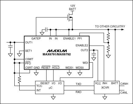
Figure 6. This automotive linear regulator contains two linear regulators plus a set of "housekeeping" functions. It can dissipate 2.7W at 70°C.
When you turn off the motor, however, the car battery must immediately deliver all currents demanded by the various subsystems: windshield wiper-blade motors, window lifters, radio/CD player/stereos, and any of the "comfort electronics systems" now found in most cars. Even when all passengers have left the car, many systems draw a keep-alive current to be ready for wake-up when their service is next required. Keeping these quiescent currents as low as possible requires linear regulators with low quiescent current as well as combinations of linear and switch-mode regulators. This article discusses the problem of minimizing quiescent current and introduces some solutions.
Alternators Deliver Plenty of Power
The typical automobile alternator can deliver about 3000W. Assuming a 14V output, that allows a current draw of more than 200A. Even with the air conditioner fully on and the car radio playing at discothèque level, the alternator's capacity can supply any combination of electrical loads in the car. Nobody has to worry about quiescent currents. But, what happens when the motor is off?The car battery can deliver all the power required—for a while! An average car battery's key specification is its capacity, measured in ampere-hours (Ah). For compact cars, a typical battery provides about 50Ah. In theory, that means that you can draw 1A for 50 hours. Doubling the current reduces the time to half. Starting the car, for example, takes several hundreds of amperes, but only for a short time. Assuming an average current draw of 300A during starting, you should have exactly ten minutes to start the engine before exhausting the battery.
Another example is lighting. Normally, a car has two front bulbs at 50W each and two rear bulbs at 20W each. Together, they consume about 140W. If you forget to switch them off when you leave the car, they will draw about 11.5A from an average 12V system. Assuming the battery is fully charged, you should have four hours before the lights extinguish automatically! In practice, the lights will extinguish earlier than that, and you will not have the ten minutes mentioned above for starting the engine either.
Typical car batteries have only 36Ah to 100Ah of capacity, depending on the car size and type. Several effects reduce the available capacity of a car battery. Colder outside temperatures, for instance, slow the internal chemical reactions. Only half the original capacity is available at -20°C. Older car batteries have less available capacity, and the battery in a car driven repeatedly for short distances (as for running errands in a town) discharges much more rapidly than that of a car used predominantly for long-distance driving. (Normally, a car must be driven for at least half an hour to recharge its full capacity.) The number of charging cycles is approximately 500 for a car that repeatedly discharges its battery by only 30%. Thus, short trips exhaust a battery more quickly and shorten its lifetime. You should expect to replace your car battery every five years.
Always-On Functions Always Consume Power
Imagine a cold winter with temperatures below zero for weeks at a time. You drive your 4-year-old car, used mainly for city driving, to the airport where you escape for a warm and sunny 3-week vacation. On your return, the car probably will not start! Its capacity has been reduced, and not only by the city driving, the elapsed parking time, and the frosty temperatures. Other, hidden energy thieves have been at work. The always-on functions in a modern car draw battery current continuously: anti-theft protection, alarm system, keyless entry receiver, and tire-pressure measurement system, to name a few. Moreover, certain nodes on the CAN bus are constantly "listening" to the bus so they can wake up immediately when their support is needed.Depending on the manufacturers and on the total number of such nodes, all these separate small quiescent currents can sum to several milliamps, or perhaps as much as 100mA of continuous current from the battery. Now, consider again the car at the airport: cold weather, city traffic, and age had possibly already reduced the available capacity to the half its nominal value. Thus the battery had only 25Ah left when the car was parked. Given a continuous quiescent current of only 25mA, the capacity lost over 21 days is 12.6Ah. As that amount is removed from the battery just while it is parked, the remainder of battery capacity is reduced to a quarter of the original value. The resulting capacity might not be enough to start a cold motor!
Caution: High Voltage
As a response to the problem of reduced, or exhausted batter capacity, car electronics systems—even those without an always-on or standby mode—constantly need power-supply options that minimize their quiescent current. Small linear regulators made with CMOS seem to be a good idea, because some such devices draw very little quiescent current indeed. The MAX1725, for instance, draws a mere 2µA. Unfortunately, however, the power supply must also have a wide input-voltage range to handle the so-called load-dump pulse, which is a brief but severe overvoltage caused by disconnecting the battery while the alternator is running.Because the alternator's control loop is not fast enough to close, it generates a high output-voltage pulse when the battery voltage is removed. This high-energy pulse is normally clamped to a lower voltage at some central location in the car, but car manufacturers also specify to their suppliers the remaining overvoltage to be expected at the inputs of their power supplies. This spec differs among car manufacturers, but the typical peak value is 36V in cars and 58V in trucks. Some values are even higher. The duration of a typical load-dump pulse is several tenths of a second (Figure 1).
Figure 1. This typical load-dump overvoltage pulse reaches a maximum amplitude (Vs) of 36V in cars and 58V in trucks. Its duration (td) is several hundred milliseconds.
Power Dissipation and Temperature
These high input-voltage levels lead us directly to the next point to consider. The linear regulator not only must withstand the overvoltage specified, it must also dissipate considerable power when delivering a high load current at low output voltage. Converting a car's typical 13V input to 5V with a 50mA load might not be critical—that is only 400mW of dissipation and just within the maximum rating for a standard SO8 package. During the overvoltage condition described above, however, the power-dissipation level at 36V increases to more than 1.5W.All packages derate their power-dissipation capability with increasing temperature, so that amount of dissipation could become a problem at higher temperatures. A regulator IC in a regular SO8 package would quickly go into thermal shutdown. The regulator would survive and resume operation after it cooled down, but that does not help because we need to keep the function alive. Automotive linear regulators need advanced packages capable of high power dissipation.
A standard automotive linear regulator like the MAX5084 is designed to operate over the automotive temperature range. It has a 65V input range, 50µA typical quiescent current, and a guaranteed output current of 200mA. Its 6-pin TDFN package with exposed pad is capable of 1.9W continuous power dissipation at +70°C, but (as for all packages) that capability is derated at higher temperatures (Figure 2). At +125°C, this package is still capable of dissipating more power than does the standard SO8 package at room temperature. Additional device features include a Kelvin-sense option that controls the output voltage directly at the load, a SET pin that programs output voltages other than the standard 3.3V and 5V, and an Enable function. If the standby function is not needed, you can disable the device which lowers the typical supply current to 6µA.
Figure 2. This small but powerful automotive linear regulator comes in a 6-pin TDFN package, and can dissipate up to 1.9W. At the maximum-allowed ambient temperature (+125°C) it can dissipate 600mW.
Lowest Possible Quiescent Current for Always-On Functions
The receiver of a remote keyless entry (RKE) system (Figure 3) must be always active, so at any time it can detect the commands issued by the remote controller in the key. You cannot disable the power supply of an RKE receiver, so its circuitry should draw the lowest possible quiescent current, especially in stand-by mode. It must then supply a normal operating current as soon as it awakens.Figure 3. A typical RKE system consists of the car-mounted side and the key-mounted side. Because the car's power supply block connects directly to the battery, its quiescent current must be low.
We must, therefore, optimize the power supply block (top left corner) in terms of minimizing quiescent current. Aside from low quiescent current, requirements on the internal linear regulator are not very stringent. It must simply provide an input, an output, and a ground pin. Shutdown and Enable functions are not required because the receiver is always powered. But, we must look closely at the way it sets the output voltage. Many linear regulators set the output voltage using an external resistor-divider, but that is probably not a good idea for this application. Consider the following scenario.
The MAX1470 RF receiver operates on a 3.3V supply. To ensure its low quiescent current we cannot allow a significant bias current in the resistor-divider. For a maximum current of 2µA, the divider resistance must be no less than 1.65MΩ. That value is available in a chip resistor, but high values have other drawbacks. They make the divider sensitive to distortion that could influence the linear regulator's output voltage.
Another major objection to the use of external resistor-dividers is that car manufacturers anticipate the long-term deposit of a parasitic dirt layer formed by oil, dirt, dust, evaporated plastic, and other particles on the PCB. Thus, the high impedance of the divider tends to decrease over time, as the parasitic layer forms parallel resistances. Direct consequences of this contamination are a slow but continuous change in the output voltage, and a steadily increasing quiescent current. Fixed-output linear regulators containing an internal divider are therefore preferred.
Given these considerations, the MAX15006 linear regulator is a good choice (Figure 4). Its small 6-pin TDFN package is capable of dissipating 1.5W, and it comes with a fixed output voltage of either 3.3V or 5V (other voltages are available upon request). The MAX15006's input voltage range (to 40V, max) allows a direct connection to the car battery, but the main advantage is an ultra-low no-load quiescent current of 9.5µA typical. For a 1mA load, the maximum quiescent current over the automotive temperature range is only 19µA, increasing to 110µA at the maximum load current of 50mA. This performance is acceptable, because the maximum supply current for the MAX1470 receiver in our example is well below 10mA.
Figure 4. This automotive linear regulator requires a minimum number of pins and external components, minimal board space, and a minimum (typical) no-load supply current of 9.5µA.
Power-Dissipation Problems
To save board space and cost, designers sometimes avoid the use of a switch-mode power supply, even when the application is pushing the linear regulator to the edge of its power-dissipation capability. Consider, for example, an automotive electrical control unit (ECU) that requires a 5V supply voltage. The ECU normally includes a microcontroller, a sensor, and a CAN driver or other bus-interface device with minor analog circuitry connected to it. It might draw 150mA of supply current in full operation.A linear regulator with 13V nominal input voltage can, therefore, dissipate 1.2W, and that level can rise briefly to 4W during a load dump. To handle the nominal 26V found in a truck, the regulator must dissipate more than 3W continuously. For these applications, another automotive linear regulator (MAX5087) has been designed for output currents as large as 400mA. It also comes in a larger 8mm x 8mm, 56-pin QFN package that boosts the allowable power dissipation to 3.8W (Figure 5).
Figure 5. One package option for the MAX5087 linear regulator is a 56-pin QFN, which increases its maximum allowable power dissipation to 3.8W.
For applications that require "housekeeping" features, the best choice is a MAX6791 linear regulator (Figure 6). Its 20-pin QFN package can dissipate 2.7W, and one of its dual linear regulators can generate a second supply voltage: 3.3V for a microprocessor and 5V for a CAN transceiver, for example. Other features include a watchdog with programmable trigger window, a power-on reset, a power-fail comparator for monitoring an additional supply voltage, and driver logic for an external power MOSFET (intended to replace a bulky and power-dissipating reverse-current protection diode).
Figure 6. This automotive linear regulator contains two linear regulators plus a set of "housekeeping" functions. It can dissipate 2.7W at 70°C.
评论