NXP LPC3240+JN5168智能家居网关方案

智能家居网关,具备智能家居控制枢纽及无线路由两大功能,负责具体的安防报警,家电控制,用电信息采集.通过无线方式与智能交互终端等产品进行数据交互.本文介绍了采用LPC3240和JN5168组成家庭网关的框图,以及完整的网关系统组成部分,基于NFC的家庭网关框图.
The LPC3220/30/40/50 embedded microcontrollers were designed for low power, high performance applications. NXP achieved their performance goals using a 90 nanometer process to implement an ARM926EJ-S CPU core with a vector floating point co-processor and a large set of standard peripherals including USB On-The-Go. The LPC3220/30/40/50 operates at CPU frequencies of up to 266 MHz.
The NXP implementation uses a ARM926EJ-S CPU core with a Harvard architecture, 5-stage pipeline, and an integral Memory Management Unit (MMU). The MMU provides the virtual memory capabilities needed to support the multi-programming demands of modern operating systems. The ARM926EJ-S also has a hardware based set of DSP instruction extensions, which includes single cycle MAC operations, and hardware based nativeJazelle Java Byte-code execution. The NXP implementation has a 32 kB instruction cache and a 32 kB data cache.
For low power consumption, the LPC3220/30/40/50 takes advantage of NXP’s advanced technology development to optimize intrinsic power and uses software controlled architectural enhancements to optimize application based power management. The LPC3220/30/40/50 also includes 256 kB of on-chip static RAM, a NAND flash interface, an Ethernet MAC, an LCD controller that supports STN and TFT panels, and an external bus interface that supports SDR and DDR SDRAM as well as static devices. In addition, the LPC3220/30/40/50 includes a USB 2.0 full-speed interface, seven UARTs,two I2C-bus interfaces, two SPI/SSP ports, two I2S-bus interfaces, two single output PWMs, a motor control PWM, six general purpose timers with capture inputs and compare outputs, a Secure Digital (SD) interface, and a 10-bit Analog-to-Digital Converter (ADC)with a touch screen sense option.
LPC3220/30/40/50主要特性和优势:
ARM926EJ-S processor, running at CPU clock speeds up to 266 MHz.
Vector Floating Point (VFP) coprocessor.
32 kB instruction cache and 32 kB data cache.
Up to 256 kB of Internal SRAM (IRAM).
Selectable boot-up from various external devices: NAND flash, SPI memory, USB,UART, or static memory.
Multi-layer AHB system that provides a separate bus for each AHB master, including both an instruction and data bus for the CPU, two data busses for the DMA controller,and another bus for the USB controller, one for the LCD, and a final one for the Ethernet MAC. There are no arbitration delays in the system unless two masters attempt to access the same slave at the same time.
External memory controller for DDR and SDR SDRAM as well as for static devices.
Two NAND flash controllers: One for single-level NAND flash devices and the other for multi-level NAND flash devices.
Master Interrupt Controller (MIC) and two Slave Interrupt Controllers (SIC), supporting 74 interrupt sources.
Eight channel General Purpose DMA (GPDMA) controller on the AHB that can be used with the SD card port, the high-speed UARTs, I2S-bus interfaces, and SPI interfaces, as well as memory-to-memory transfers.
Serial interfaces:
10/100 Ethernet MAC with dedicated DMA Controller.
USB interface supporting either device, host (OHCI compliant), or On-The-Go(OTG) with an integral DMA controller and dedicated PLL to generate the required 48 MHz USB clock.
Four standard UARTs with fractional baud rate generation and 64 byte FIFOs. One of the standard UARTs supports IrDA.
Three additional high-speed UARTs intended for on-board communications that support baud rates up to 921 600 when using a 13 MHz main oscillator. Allhigh-speed UARTs provide 64 byte FIFOs.
Two SPI controllers.
Two SSP controllers.
Two I2C-bus interfaces with standard open-drain pins. The I2C-bus interfaces support single master, slave, and multi-master I2C-bus configurations.
Two I2S-bus interfaces, each with separate input and output channels. Each
channel can be operated independently on three pins, or both input and output
channels can be used with only four pins and a shared clock.
Additional peripherals:
LCD controller supporting both STN and TFT panels, with dedicated DMA
controller. Programmable display resolution up to 1024 768.
Secure Digital (SD) memory card interface, which conforms to the SD Memory
Card Specification Version 1.01.
General Purpose (GP) input, output, and I/O pins. Includes 12 GP input pins, 24 GP output pins, and 51 GP I/O pins.
10-bit, 400 kHz Analog-to-Digital Converter (ADC) with input multiplexing from three pins. Optionally, the ADC can operate as a touch screen controller.
Real-Time Clock (RTC) with separate power pin and dedicated 32 kHz oscillator.
NXP implemented the RTC in an independent on-chip power domain so it can
remain active while the rest of the chip is not powered. The RTC also includes a 32-byte scratch pad memory.
32-bit general purpose high-speed timer with a 16-bit pre-scaler. This timer includes one external capture input pin and a capture connection to the RTC clock.
Interrupts may be generated using three match registers.
Six enhanced timer/counters which are architecturally identical except for the peripheral base address. Two capture inputs and two match outputs are pinned out to four timers. Timer 1 brings out a third match output, timers 2 and 3 bring out all four match outputs, timer 4 has one match output, and timer 5 has no inputs or outputs.
32-bit millisecond timer driven from the RTC clock. This timer can generate interrupts using two match registers.
WatchDog timer clocked by the peripheral clock.
Two single-output PWM blocks.
Motor control PWM.
Keyboard scanner function allows automatic scanning of an up to 8 8 key matrix.
Up to 18 external interrupts.
Standard ARM test/debug interface for compatibility with existing tools.
Emulation Trace Buffer (ETB) with 2048 24 bit RAM allows trace via JTAG.
Stop mode saves power while allowing many peripheral functions to restart CPU activity.
On-chip crystal oscillator.
An on-chip PLL allows CPU operation up to the maximum CPU rate without the
requirement for a high frequency crystal. Another PLL allows operation from the 32 kHz RTC clock rather than the external crystal.
Boundary scan for simplified board testing.
User-accessible unique serial ID number for each chip.
TFBGA296 package with a 15 mmx15 mmx0.7 mm body.
LPC3220/30/40/50应用:
Consumer
Medical
Industrial
Network control
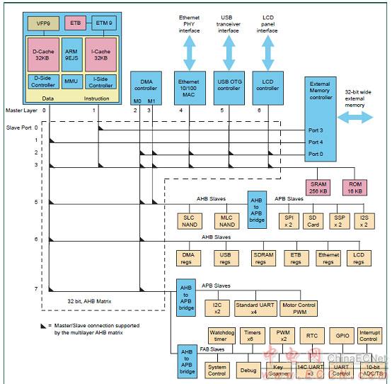
图1。LPC3220/30/40/50框图
The NXP Internet of Things (IoT) Gateway is an essentialcomponent for connecting everyday wireless-enabled devicesto the wired internet so they can be controlled and monitored.
The powerful ARM9-based host controller runs an OpenWRTLinux operating system, providing an easy-to-use platformfor system development. The software is modular, allowingfor easy customization, including changes to the applicationsoftware. The wireless interface can participate in ZigBeeor JenNet-IP networks. With the addition of a wireless USBdongle, the gateway can participate in a mix of both networks.
Data encryption uses standard internet techniques on thewired interface, and 128-bit AES encryption for wirelesscommunications.
图2。NXP IOT网关外形图
IOT网关主要优势:
``JN5168 ZigBee / JenNet-IP wireless interface
``Provides a single application layer for ZigBee Light Link,ZigBee Home Automation, and JenNet-IP
``Custom software enables hybrid ZigBee Home Automation /ZigBee Light Link networks
``MIB-based JIP application layer
`` OpenWRT Linux operating system
`` Programmable for custom applications
`` Supports standard internet security, including TLS
`` Supports local web server
`` NXP LPC3240 ARM9 host controller
`` 1 GB Flash
`` 512 kB SRAM
`` 256 kB EEPROM
`` 7-16 V DC power supply input
`` Ethernet RJ45 port
`` USB port supports WiFi dongle or additional network layer
`` CE and FCC certified
`` Customizable LED and button functions
`` External antenna with RP-SMA connector
IOT网关应用:
`` Internet control of ZigBee networks
`` I nternet control of JenNet-IP networks
`` Ethernet connected gateway/coordinator
`` Floor or room controller in commercial buildings

图3。IOT网关框图
家庭网络应用笔记
This Application Note provides software for a Smart Home network allowing the control and monitoring of Smart Devices via standard Internet Protocol messages over a low power radio network.
Smart Devices can be controlled and monitored from within the low power radio network and also, with the addition of a JenNet-IP Gateway, from a standard Local Area Network and even a Wide Area Network such as the internet.
The Application Note includes software for the following Smart Devices:
Bulb software allowing the bulb to be turned on, off and dimmed remotely. Plus monitoring of on-time and counter for bulbs being turned on. White, colour controlled temperature and full colour bulbs are all supported.
Sensor software allowing the monitoring of occupancy and/or illuminance with optional control of bulb devices.
Remote control providing control of Smart Devices from a small touch sensitive device.
Low energy switch providing limited control of Smart Devices from a coin cell or energy harvesting device. JenNet-IP networks can operate in one of three modes:
Gateway Mode includes a gateway device allowing access to the low-power wireless Smart Devices from other Internet Protocol devices connected via the local IP network, Wi-Fi or even from the external internet. Smart Devices can also be controlled by other Smart Devices within the low power wireless network such as remote controls and sensors. This system provides the most flexibility and options for controlling and monitoring Smart Devices.
Coordinator Mode replaces the gateway device with a simple Coordinator device. This effectively creates a network from only the low power wireless Smart Devices and so does not allow connections to a local IP network or the internet.
Standalone Mode does not include a gateway device. The Smart Devices form a low power wireless network that can only be controlled by other Smart Devices from within the network such as the remote control included in JenNet-IP Smart Home (JN-AN-1162). This type of system provides a low cost entry point for building a Smart Device system while allowing a gateway device to be added later.

图4。IOT网关系统框图
完整的网关系统包括:
Routers
The IP routers, provide Internet Protocol routing services for devices in the network. This provides standard IP routing of packets in the LAN and WAN domains via standard internet router devices.
Commands from devices in the LAN or WAN can be passed into the WPAN via the JenNet-IP gateway using cabled Ethernet connections or Wi-Fi links as shown by the solid and dotted grey lines in the LAN and WAN domains of the gateway system topology diagram.
Gateway
Adding a JenNet-IP gateway device to the internet router extends the IP network into the WPAN domain providing low power wireless access to the Smart Device network. The JenNet-IP gateway includes a border router device, (either internally or externally), which provides the WPAN radio services.
Commands sent to individual devices in the WPAN follow the tree structure of the JenNet-IP network, (represented by the dotted grey lines in the WPAN domain of the gateway system topology diagram).
Commands broadcast to groups of devices are simply broadcast to every device in range of the original transmission, receiving devices then re-broadcast the commands ensuring that they reach every device in the network. Only the devices that are members of the group the command is addressed to will take any action (such as turning on a bulb) upon receipt of a group broadcast (though all devices re-broadcast to ensure the command reaches all devices in the network).
Smart Devices
Bulbs: allow wireless control of lighting in the home. These devices act as router nodes in the low power JenNet-IP wireless network extending the network for other Smart Devices to join.
Sensors: monitor occupancy and light levels in an area and can control the bulbs based upon their readings.
Remote controls: allow control of other Smart Devices in the low power JenNet-IP wireless network. These devices operate as sleeping broadcaster devices in order to allow mobile operation and preserve battery life. To do this they spend most of their time asleep, thus preserving power, only waking to read button inputs. Commands are always broadcast to a group of devices so the remote control does not need to maintain a full connection to the network. This allows the remote control to be freely moved around the area covered by the WPAN.
In a gateway system the Smart Devices form a JenNet-IP tree network allowing messages to be directed to both individual nodes in the form of unicasts and groups of nodes in the form of broadcasts from within the wireless PAN and any connected LAN or WAN.
基于NFC的家庭网关
A growing number of homes use a WiFi router to make Internet access more convenient, and now, as homes become more connected and the number of Internet-ready devices continues to expand, the router is truly the heart of home-based Internet of Things (IoT) networks.

图5。基于NFC的家庭网关框图
The router acts as a home gateway, providing Internet access to everything from mobile phones and laptops to appliances like washing machines and refrigerators, wearables, thermostats, multimedia players, and even fish tanks.
With NFC, the router can send credentials to any new device equipped with an NFC tag, for quick commissioning, and the consumer’s NFC-enabled smartphone or tablet can be used as a bridge, to make the interaction even easier.
The NFC IC inside the router generates the necessary RF field for communication, so the device being commissioned doesn’t need to be powered, and that saves energy.

The LPC3220/30/40/50 embedded microcontrollers were designed for low power, high performance applications. NXP achieved their performance goals using a 90 nanometer process to implement an ARM926EJ-S CPU core with a vector floating point co-processor and a large set of standard peripherals including USB On-The-Go. The LPC3220/30/40/50 operates at CPU frequencies of up to 266 MHz.
The NXP implementation uses a ARM926EJ-S CPU core with a Harvard architecture, 5-stage pipeline, and an integral Memory Management Unit (MMU). The MMU provides the virtual memory capabilities needed to support the multi-programming demands of modern operating systems. The ARM926EJ-S also has a hardware based set of DSP instruction extensions, which includes single cycle MAC operations, and hardware based nativeJazelle Java Byte-code execution. The NXP implementation has a 32 kB instruction cache and a 32 kB data cache.
For low power consumption, the LPC3220/30/40/50 takes advantage of NXP’s advanced technology development to optimize intrinsic power and uses software controlled architectural enhancements to optimize application based power management. The LPC3220/30/40/50 also includes 256 kB of on-chip static RAM, a NAND flash interface, an Ethernet MAC, an LCD controller that supports STN and TFT panels, and an external bus interface that supports SDR and DDR SDRAM as well as static devices. In addition, the LPC3220/30/40/50 includes a USB 2.0 full-speed interface, seven UARTs,two I2C-bus interfaces, two SPI/SSP ports, two I2S-bus interfaces, two single output PWMs, a motor control PWM, six general purpose timers with capture inputs and compare outputs, a Secure Digital (SD) interface, and a 10-bit Analog-to-Digital Converter (ADC)with a touch screen sense option.
LPC3220/30/40/50主要特性和优势:
ARM926EJ-S processor, running at CPU clock speeds up to 266 MHz.
Vector Floating Point (VFP) coprocessor.
32 kB instruction cache and 32 kB data cache.
Up to 256 kB of Internal SRAM (IRAM).
Selectable boot-up from various external devices: NAND flash, SPI memory, USB,UART, or static memory.
Multi-layer AHB system that provides a separate bus for each AHB master, including both an instruction and data bus for the CPU, two data busses for the DMA controller,and another bus for the USB controller, one for the LCD, and a final one for the Ethernet MAC. There are no arbitration delays in the system unless two masters attempt to access the same slave at the same time.
External memory controller for DDR and SDR SDRAM as well as for static devices.
Two NAND flash controllers: One for single-level NAND flash devices and the other for multi-level NAND flash devices.
Master Interrupt Controller (MIC) and two Slave Interrupt Controllers (SIC), supporting 74 interrupt sources.
Eight channel General Purpose DMA (GPDMA) controller on the AHB that can be used with the SD card port, the high-speed UARTs, I2S-bus interfaces, and SPI interfaces, as well as memory-to-memory transfers.
Serial interfaces:
10/100 Ethernet MAC with dedicated DMA Controller.
USB interface supporting either device, host (OHCI compliant), or On-The-Go(OTG) with an integral DMA controller and dedicated PLL to generate the required 48 MHz USB clock.
Four standard UARTs with fractional baud rate generation and 64 byte FIFOs. One of the standard UARTs supports IrDA.
Three additional high-speed UARTs intended for on-board communications that support baud rates up to 921 600 when using a 13 MHz main oscillator. Allhigh-speed UARTs provide 64 byte FIFOs.
Two SPI controllers.
Two SSP controllers.
Two I2C-bus interfaces with standard open-drain pins. The I2C-bus interfaces support single master, slave, and multi-master I2C-bus configurations.
Two I2S-bus interfaces, each with separate input and output channels. Each
channel can be operated independently on three pins, or both input and output
channels can be used with only four pins and a shared clock.
Additional peripherals:
LCD controller supporting both STN and TFT panels, with dedicated DMA
controller. Programmable display resolution up to 1024 768.
Secure Digital (SD) memory card interface, which conforms to the SD Memory
Card Specification Version 1.01.
General Purpose (GP) input, output, and I/O pins. Includes 12 GP input pins, 24 GP output pins, and 51 GP I/O pins.
10-bit, 400 kHz Analog-to-Digital Converter (ADC) with input multiplexing from three pins. Optionally, the ADC can operate as a touch screen controller.
Real-Time Clock (RTC) with separate power pin and dedicated 32 kHz oscillator.
NXP implemented the RTC in an independent on-chip power domain so it can
remain active while the rest of the chip is not powered. The RTC also includes a 32-byte scratch pad memory.
32-bit general purpose high-speed timer with a 16-bit pre-scaler. This timer includes one external capture input pin and a capture connection to the RTC clock.
Interrupts may be generated using three match registers.
Six enhanced timer/counters which are architecturally identical except for the peripheral base address. Two capture inputs and two match outputs are pinned out to four timers. Timer 1 brings out a third match output, timers 2 and 3 bring out all four match outputs, timer 4 has one match output, and timer 5 has no inputs or outputs.
32-bit millisecond timer driven from the RTC clock. This timer can generate interrupts using two match registers.
WatchDog timer clocked by the peripheral clock.
Two single-output PWM blocks.
Motor control PWM.
Keyboard scanner function allows automatic scanning of an up to 8 8 key matrix.
Up to 18 external interrupts.
Standard ARM test/debug interface for compatibility with existing tools.
Emulation Trace Buffer (ETB) with 2048 24 bit RAM allows trace via JTAG.
Stop mode saves power while allowing many peripheral functions to restart CPU activity.
On-chip crystal oscillator.
An on-chip PLL allows CPU operation up to the maximum CPU rate without the
requirement for a high frequency crystal. Another PLL allows operation from the 32 kHz RTC clock rather than the external crystal.
Boundary scan for simplified board testing.
User-accessible unique serial ID number for each chip.
TFBGA296 package with a 15 mmx15 mmx0.7 mm body.
LPC3220/30/40/50应用:
Consumer
Medical
Industrial
Network control
图1。LPC3220/30/40/50框图
The NXP Internet of Things (IoT) Gateway is an essentialcomponent for connecting everyday wireless-enabled devicesto the wired internet so they can be controlled and monitored.
The powerful ARM9-based host controller runs an OpenWRTLinux operating system, providing an easy-to-use platformfor system development. The software is modular, allowingfor easy customization, including changes to the applicationsoftware. The wireless interface can participate in ZigBeeor JenNet-IP networks. With the addition of a wireless USBdongle, the gateway can participate in a mix of both networks.
Data encryption uses standard internet techniques on thewired interface, and 128-bit AES encryption for wirelesscommunications.
图2。NXP IOT网关外形图
IOT网关主要优势:
``JN5168 ZigBee / JenNet-IP wireless interface
``Provides a single application layer for ZigBee Light Link,ZigBee Home Automation, and JenNet-IP
``Custom software enables hybrid ZigBee Home Automation /ZigBee Light Link networks
``MIB-based JIP application layer
`` OpenWRT Linux operating system
`` Programmable for custom applications
`` Supports standard internet security, including TLS
`` Supports local web server
`` NXP LPC3240 ARM9 host controller
`` 1 GB Flash
`` 512 kB SRAM
`` 256 kB EEPROM
`` 7-16 V DC power supply input
`` Ethernet RJ45 port
`` USB port supports WiFi dongle or additional network layer
`` CE and FCC certified
`` Customizable LED and button functions
`` External antenna with RP-SMA connector
IOT网关应用:
`` Internet control of ZigBee networks
`` I nternet control of JenNet-IP networks
`` Ethernet connected gateway/coordinator
`` Floor or room controller in commercial buildings
图3。IOT网关框图
家庭网络应用笔记
This Application Note provides software for a Smart Home network allowing the control and monitoring of Smart Devices via standard Internet Protocol messages over a low power radio network.
Smart Devices can be controlled and monitored from within the low power radio network and also, with the addition of a JenNet-IP Gateway, from a standard Local Area Network and even a Wide Area Network such as the internet.
The Application Note includes software for the following Smart Devices:
Bulb software allowing the bulb to be turned on, off and dimmed remotely. Plus monitoring of on-time and counter for bulbs being turned on. White, colour controlled temperature and full colour bulbs are all supported.
Sensor software allowing the monitoring of occupancy and/or illuminance with optional control of bulb devices.
Remote control providing control of Smart Devices from a small touch sensitive device.
Low energy switch providing limited control of Smart Devices from a coin cell or energy harvesting device. JenNet-IP networks can operate in one of three modes:
Gateway Mode includes a gateway device allowing access to the low-power wireless Smart Devices from other Internet Protocol devices connected via the local IP network, Wi-Fi or even from the external internet. Smart Devices can also be controlled by other Smart Devices within the low power wireless network such as remote controls and sensors. This system provides the most flexibility and options for controlling and monitoring Smart Devices.
Coordinator Mode replaces the gateway device with a simple Coordinator device. This effectively creates a network from only the low power wireless Smart Devices and so does not allow connections to a local IP network or the internet.
Standalone Mode does not include a gateway device. The Smart Devices form a low power wireless network that can only be controlled by other Smart Devices from within the network such as the remote control included in JenNet-IP Smart Home (JN-AN-1162). This type of system provides a low cost entry point for building a Smart Device system while allowing a gateway device to be added later.
图4。IOT网关系统框图
完整的网关系统包括:
Routers
The IP routers, provide Internet Protocol routing services for devices in the network. This provides standard IP routing of packets in the LAN and WAN domains via standard internet router devices.
Commands from devices in the LAN or WAN can be passed into the WPAN via the JenNet-IP gateway using cabled Ethernet connections or Wi-Fi links as shown by the solid and dotted grey lines in the LAN and WAN domains of the gateway system topology diagram.
Gateway
Adding a JenNet-IP gateway device to the internet router extends the IP network into the WPAN domain providing low power wireless access to the Smart Device network. The JenNet-IP gateway includes a border router device, (either internally or externally), which provides the WPAN radio services.
Commands sent to individual devices in the WPAN follow the tree structure of the JenNet-IP network, (represented by the dotted grey lines in the WPAN domain of the gateway system topology diagram).
Commands broadcast to groups of devices are simply broadcast to every device in range of the original transmission, receiving devices then re-broadcast the commands ensuring that they reach every device in the network. Only the devices that are members of the group the command is addressed to will take any action (such as turning on a bulb) upon receipt of a group broadcast (though all devices re-broadcast to ensure the command reaches all devices in the network).
Smart Devices
Bulbs: allow wireless control of lighting in the home. These devices act as router nodes in the low power JenNet-IP wireless network extending the network for other Smart Devices to join.
Sensors: monitor occupancy and light levels in an area and can control the bulbs based upon their readings.
Remote controls: allow control of other Smart Devices in the low power JenNet-IP wireless network. These devices operate as sleeping broadcaster devices in order to allow mobile operation and preserve battery life. To do this they spend most of their time asleep, thus preserving power, only waking to read button inputs. Commands are always broadcast to a group of devices so the remote control does not need to maintain a full connection to the network. This allows the remote control to be freely moved around the area covered by the WPAN.
In a gateway system the Smart Devices form a JenNet-IP tree network allowing messages to be directed to both individual nodes in the form of unicasts and groups of nodes in the form of broadcasts from within the wireless PAN and any connected LAN or WAN.
基于NFC的家庭网关
A growing number of homes use a WiFi router to make Internet access more convenient, and now, as homes become more connected and the number of Internet-ready devices continues to expand, the router is truly the heart of home-based Internet of Things (IoT) networks.
图5。基于NFC的家庭网关框图
The router acts as a home gateway, providing Internet access to everything from mobile phones and laptops to appliances like washing machines and refrigerators, wearables, thermostats, multimedia players, and even fish tanks.
With NFC, the router can send credentials to any new device equipped with an NFC tag, for quick commissioning, and the consumer’s NFC-enabled smartphone or tablet can be used as a bridge, to make the interaction even easier.
The NFC IC inside the router generates the necessary RF field for communication, so the device being commissioned doesn’t need to be powered, and that saves energy.
评论
看看学学