
xTimer V1.0

Figure 1: The prototype of xTiemr V1.0.
The LED module with MAX7219 is a ready made having 10-pin header for easy plugin to the 4051 board. As shown in Fig. 1, four keys are used to set time for each timer. Each timer will have two digit LED. The right hand side, timer 1 and timer 2 are for minute counting, the left hand, timer 3 and timer 4 are for hour counting.
For easy setting with key switch, it has a preset time value that was commonly used, e.g. -1, 0, 3, 5, 10, 15, 20, 25.
When time-out, display will show 0, and the output bit is activated. The optional two buzzers are for timer1 and timer2 alarm. I made this output alarm for kitchen use.
Hardware Schematic
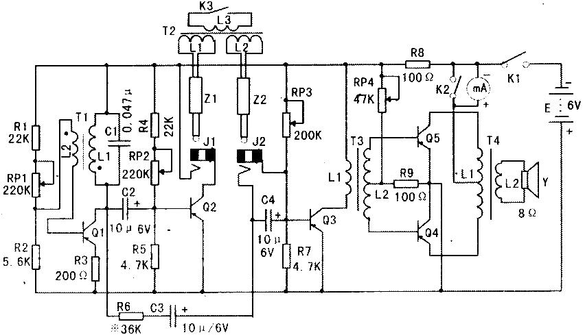
Complete schematic is shown in Fig 2. The MCU is AT89C4051 with 11.0592MHz xtal. The MAX7219 needs only three signals, CLK, DIN and LOAD. These signals are software generated assembly code. You may learn how assembly code interface with c from the firmware. Since when power up, all port bits are logic high, so I chose the 7407, open collector to provide NPN O/C output. These output bits are suitable for opto-isolator driving. The sample output module is opto-triac, the MC3040. The input circuit is simple with current mode driving, say 15mA is enough for MC3040. The output triac having ZCS drives a 220V coil electromechanical relay. Since the relay contact provide NO and NC, so we can provide two function AC plugs, i.e., delay on for NO and delay off for NC contacts.
Figure 2: Hardware schematic of xTimer V1.0.

xtimer1.pdf
You can notice that we have reset button to wake up MCU! This version has no main switch to power on and off the board. Instead it uses MCU and MAX7219 power down mode. We will see later sample code that put MCU and MAX7219 to power down mode. When All LEDs are light, the dc current drawn about 90mA @ 5V, and when power down mode, it will be approx. 10mA. The circuit of MAX7219 is recommenced by MAXIM application note, it is simple hardware and most of settings are done by software control.
Software
Main program is simple forever loop with 10ms tick cycle. All tasks will run every tick in round robin manner. The tick was prepared in startup file, as shown below, it was declared as cputick and the modifier extern indicates this variable was declared in external file.
extern unsigned register char cputick;
Here is the main program, we will see detail for each task below.
while(1)
{
while(!cputick) // run following tasks every 10ms
;
cputick = 0;
set_timer(); // check key pressed
run_timer(); // run four timers
key_release(); // check if key has been released
updatedisplay(); // send data to MAX7219
ring1(); // optional buzzer alarm1
ring2(); // optional buzzer alarm2
}
set_timer( ) function will check a given input bit. These input bit are P3.2, P3.3, P3.4 and P3.7. Checking is done by logical AND a specified bit with MASK byte, e.g. for P3.2 we will check bit 2 of P3 with MASK byte 0x04. The statement will be (P30x04), if the result is 0 then set flag1 bit 0 to one to indicates that key1 was pressed. Then check index1 greater or equal 9, if true, reset index1 to 0. Timer1 will reload with a preset_timer1[index1 ].
The preset_timer1[] array is preset value for timer1. The sample is below.
char preset_timer1[] = {-1,0,3,5,10,15,20,25,30};
// reload preset time value from preset array for each key pressed
set_timer()
{
if((flag11) == 0) // enter only when keys have been released
{
if((P30x04) == 0)
{
flag1 |= 1;
if(index1=9) index1 =0;
timer1= preset_timer1[index1 ];
}
if((P30x08) == 0)
{
flag1 |= 1;
if(index2=9) index2 =0;
timer2= preset_timer2[index2 ];
}
if((P30x10) == 0)
{
flag1 |= 1;
if(index3=13) index3 =0;
timer3= preset_timer3[index3 ];
}
if((P30x20) == 0)
{
flag1 |= 1;
if(index4=8) index4 =0;
timer4= preset_timer4[index4 ];
}
}
}
You may see every key checking, flag1 bit 0 will set. This flag will signal the set timer task that key has been pressed, so on entering it will check if this bit = 1, it will not repeat running.
The task that reset this bit will check if all keys have been released is shown below. using logical AND P3 with 0x3C. If all bits are '1', then clear bit 0 of flag1.
key_release()
{
if((P30x3c) == 0x3c)
flag1 = ~1;
}
run_timer( ) can be one second resolution, so we put it running every second with the help of incrementing of one_second variable. All four timers will run every second then. The shutdown task also runs every second. We will see later for shutdown detail.
run_timer()
{
if( one_sec=100)
{
one_sec = 0;
run_timer1();
run_timer2();
run_timer3();
run_timer4();
shutdown(); // run shutdown checking every second
}
}
Now look at the sample code that runs timer1.
run_timer1()
{
if(timer1 != -1) // enter only preset value != -1
{
if(timer1 != 0) // enter only timer1 != 0
{
timer7 = 0; // reset shutdown timeout
buzzer1 = off;
flag1 |= 0x02;
setbit(output1)
if( timer1_clk = 60) // timer1 is one min based!
{
timer1_clk = 0;
timer1--;
}
}
else // timer1 == 0 then fire output
{
clrbit(output1) // fire output1
buzzer1 = on;
flag1 = ~0x02;
flag2 = ~0x01;
}
}
else
{
flag1 = ~0x02; // no blink when timer1 == -1
flag2 = ~0x01;
buzzer1 = off;
}
}
We have three states that will be executed. Below table shows the action for each state. Note that timer7 is a timer that we used for shutdown timeout. Flag1 bit 1 is for dot blinking signal flag.
StateActionTimer1 = -1flag1 = ~0x02; // no dot blink
flag2 = ~0x01;
buzzer1 = off; // off buzzer1Timer1 = 0clrbit(output1) // fire output1
buzzer1 = on; // on buzzer flag
flag1 = ~0x02; // no dot blink
flag2 = ~0x01;Timer1 = 3, 5,....timer7 = 0; // reset shutdown timeout
buzzer1 = off;
flag1 |= 0x02;
setbit(output1)
if( timer1_clk = 60) {timer1_clk = 0;
timer1--; }
As shown above the shutdown task also resided in one second resolution the same as timer running. Timer7 will reset every timer1 is not equal 0. However when user set all timers off, or all value of timer1-timer4 will be -1, then the shutdown task will run. The timeout is 10 seconds, you may see that when timeout, the MAX7219 will be set to shutdown mode and the PD bit in PCON will be set to one to enable power down! The on chip oscillator stops!, and display will show blank. There will no response from any key pressing then. To wake up MCU and turn it on, the RESET button will help exit from power down mode!
shutdown()
{
if((timer1timer2timer3timer4)== -1)
{
timer7 ;
if(timer7 = 10) // 10 seconds timeout
{
shift(0x0c00); // enable shutdown mode
asm' CLR IE.7';
asm' MOV PCON,#2'; // enter power down mode
}
}
}
The update display will send serial data of buffer[] array to MAX7219. You may study the code of how to convert binary data to 7-segment display in moveTimetobuffer( ) function.
SDCC version firmware
Again the reason why I wrote a new version firmware, just for fun and spend my free time learning new things. I got the problem with a big electromechanical relay, mostly the makers only produce the NO contact. The sample schematic shown in Fig 2. has the relay circuit that uses opto triac driving a NO/NC relay! So I must change the firmware to let the output turn on when start timer and turn off when time is over. To do such changing, it needs to modify the source code and recompile it. I thought why don't try with sdcc. The people can modify the source code and do-it-yourself.
Let get the sdcc for dos command line, SDCC for 8051. Unzip the package and save to drive c. I made the folder app (application programs) for my source code. Here is the new source code for sdcc, xtimer1.c
Timer4 is now modified to be delay off output. The counting is now based on minute the same as timer1 and 2. Timer3 still be hour counting based. I have made the opto-relay for big load switching.
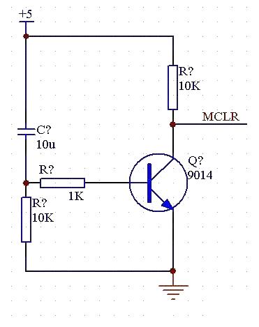
Figure 3: opto-relay for output4(active low).
The opto-transistor can be any type. Usually some opto output can drive relay directly, but I think better to use a darlington transistor, says ULN2003, ULN2803 to drive the relay. With this method, there is no galvanic contact between HV and digital board. The EMI produced from inductive load turning off will only propagate to the control board by induction and radiation. This design is quite save for digital control board.
Now get back to run sdcc, below steps show how to use sdcc to compile the source code. After the sdcc has installed in drive c:, we must set path to let the dos know where is the folder of exe files of sdcc. To compile just type sdcc program.c. If everything OK, we will get the machine code in hex file. However the hex file produced by sdcc has *.ihx extension. We can convert it to hex file with *.hex simply by a program packihx. See example below.
The hex file produced by sdcc is only 1877 bytes! You can use 89C2051 instead of 89C4051 for U2!
Microsoft(R) Windows 98
(C)Copyright Microsoft Corp 1981-1999.
C:\WINDOWScd\
C:\cd sdcc
C:\sdcccd app
C:\sdcc\apppath=c:\sdcc\bin
C:\sdcc\appsdcc xtimer1.c
library file /sdcc/share/sdcc/lib/small/libsdcc.lib
library file /sdcc/share/sdcc/lib/small/libint.lib
library file /sdcc/share/sdcc/lib/small/liblong.lib
library file /sdcc/share/sdcc/lib/small/libfloat.lib
C:\sdcc\app
C:\sdcc\apppackihx xtimer1.ihxxtimer1.hex
packihx: read 308 lines, wrote 122: OK.
C:\sdcc\app

程序资料下载.rar
评论