
12V电池升压器(英文)-----multi output power converter

12V电池升压器制作
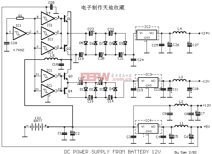
Many times we needed a variety of voltages, from a battery 12V. With the circuit, we CAN take voltages smaller or bigger, positive or negative, from a battery 12V. The idea is based in oscillator roughly 7KHz, round the R1, C28, that lead the remainder gates of IC1, that are connected at the parallel, (so that they provide the essential current of drive), that drive with the line their transistors Q1 until Q4. Then exist two circuits of "cascade" constituted from diodes and caPACitors, D1 until D4, C14 until C17 for the negative and D5 until D9, C19 until C23 for the positive voltage, that drive the corresponding stabilizers. In the outputs of stabilizers exist inductors, which they remove and the last remains of oscillation. The current that we can take from the outputs are order the 100 until 200 mA. The total time that will capacity of battery it gives the current that we want, it’s up to from her capacity on Ah, as long as more so much more time. All the transistors and the stabilizers, good it is they are placed in a heatsink, in order to it remove the produced heat.
Part List |
|
评论