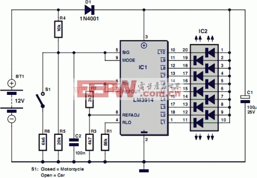
Although the circuit draws so little power that it will not noticeably load the battery under test, it should not be left connected permanently. The circuit employs the familiar LM3914 (IC1) to display the voltage level. The LED readout creates a battery status readout: when the top LED lights, the battery is fully charged. When the bottom LED lights, the battery needs imminent charging! Switch S1 selects between 12 V and 6 V operation. A series diode, D1, protects the bargraph driver from reverse supply voltage. A color-coded display with individual LEDs could be used instead of the common-anode bargraph display for better indication of the state of the battery.
(责任编辑:电路图) |


评论