LED显示数字电压表电路,Led display digit


LED显示数字电压表电路,Led display digital Voltmeter
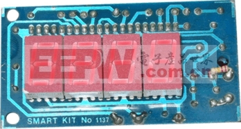
front side
Copyright of this circuit belongs to smart kit electronics. In this page we will use this circuit to discuss for improvements and we will introduce some changes based on original schematic.Supply Voltage: ............. +/- 5 V (Symmetrical)All this sounds quite easy but it is in fact a series of very complex operations which are all made by the ADC IC with the help of a few external components which are used to configure the circuit for the job. In detail the circuit works as follows. The voltage to be measured is applied across points 1 and 2 of the circuit and through the circuit R3, R4 and C4 is finally applied to pins 30 and 31 of the IC. These are the input of the IC as you can see from its diagram. (IN HIGH IN LOW respectively). The resistor R1 together with C1 are used to set the frequency of the internal oscillator (clock) which is set at about 48 Hz. At this clock rate there are about three different readings per second. The capacitor C2 which is connected between pins 33 and 34 of the IC has been selected to compensate for the error caused by the internal reference voltage and also keeps the display steady. The capacitor C3 and the resistor R5 are together the circuit that does the integration of the input voltage and at the same time prevent any division of the input voltage making the circuit faster and more reliable as the possibility of error is greatly reduced. The capacitor C5 forces the instrument to display zero when there is no voltage at its input. The resistor R2 together with P1 are used to adjust the instrument during set-up so that it displays zero when the input is zero. The resistor R6 controls the current that is allowed to flow through the displays so that there is sufficient brightness with out damaging them. The IC as we have already mentioned above is capable to drive four common anode LED displays. The three rightmost displays are connected so that they can display all the numbers from 0 to 9 while the first from the left can only display the number 1 and when the voltage is negative the «-« sign. The whole circuit operates from a symmetrical ρ 5 VDC supply which is applied at pins 1 (+5 V), 21 (0 V) and 26 (-5 V) of the IC.
Construction

PCB dimensions: 77,6mm x 44,18mm or scale it at 35%
If it does not work
评论