MAX16820典型应用电路图

For several LEDs in series, the sum of their VF voltages can go to 40V or more, and if not referenced to ground, that VF sum requires a differential measurement. As a third challenge (in addition to high voltage and differential measurement), HBLEDs are often dimmed using pulse-width modulation (PWM). If so, you can't measure VF during the low portion of the PWM duty cycle, when the LEDs are not illuminated and VF is not present. For a hysteretic buck LED driver (MAX16820) driving three LEDs in series (Figure 1), you must measure the anode and cathode voltages of the string when DIM is high.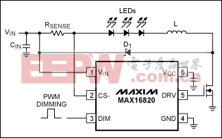
To avoid the need for a differential high-voltage measurement, you can take the indirect approach of measuring the duty cycle at the DRV pin. For this particular LED driver, a first-order estimate of forward voltage for the LED string is VF = D × VIN, where D represents an internal duty cycle produced in the IC's switchmode section (not to be confused with the duty cycle at DIM). The DRV signal is referenced to ground and limited to VCC (5V). That condition allows the use of low voltage ADCs or comparators, which in turn can be powered by the LED driver's VCC output (10mA maximum).

To avoid the need for a differential high-voltage measurement, you can take the indirect approach of measuring the duty cycle at the DRV pin. For this particular LED driver, a first-order estimate of forward voltage for the LED string is VF = D × VIN, where D represents an internal duty cycle produced in the IC's switchmode section (not to be confused with the duty cycle at DIM). The DRV signal is referenced to ground and limited to VCC (5V). That condition allows the use of low voltage ADCs or comparators, which in turn can be powered by the LED driver's VCC output (10mA maximum).
评论